Siklu - Getting Started - EtherHaul (TDD) using Quick Config Wizard
Description:
The purpose of this guide is to document the process using the Siklu Quick Config Wizard to establish a basic link using Siklu 500TX TDD Radios. This process is also applicable to other EtherHaul radios in the Siklu portfolio including FDD units where the Radio parameters will be slightly different as we will need to define different TX frequencies for each unit.
Prerequisites:
We will need to have a Network Interface configured in the 192.168.0.x subnet. The default IP Address of Siklu Radios is 192.168.0.1.
Step 1: Connecting to the Web GUI
Open your browser and navigate to https://192.168.0.1
Step 2: Login
Enter the default Username "admin" and Password "admin"
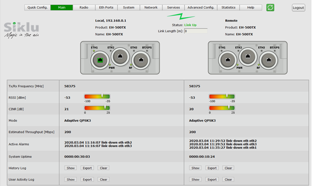
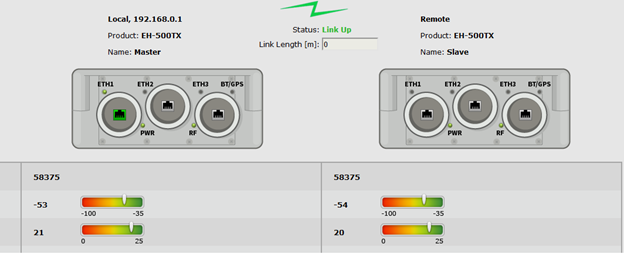
You will be presented with the Main Page as per below
If both radios are not present on this page you will need to adjust the units to achieve a link, this will be indicated by the status "Link Up". For the purposes of using the Quick Config Wizard, we will need to ensure the RSSI levels are between -55 and -35 dBm and CINR above 15dB.
Once we have a stable Link we can click on the Quick Config button
Step 3: (Quick Config Step 1 - System)
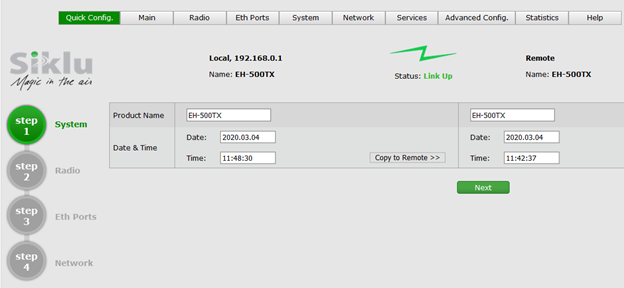
In this tab, we will define names for the units for ease of identification and the Date & Time.
In this example, our Local Unit will be labeled Master, while the Remote Unit will be labeled Slave
Once we have made changes to the Date & Time where required we can click on the Copy to Remote button and this will replicate the settings on the Remote Unit.
Click the next button to proceed.
Step 4: (Quick Config Step 2 - Radio)
In this tab, we will configure the radio parameters according to the Link Plan / Link Budget calculations.
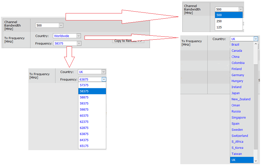
Select the Channel Bandwidth, Country and Frequency (Make sure to select a channel that is approved for use by local regulation).
Click the Copy to Remote button and this will replicate the settings on the Remote Unit.
Transmit power (default is the max power based on the product’s specs. Reduce Tx power in case of short links, making sure the RSSI at the remote radio does not exceed -35dBm (overload threshold).
In most instances, we will leave the Mode in Adaptive, however, we do have options to select Alignment Mode and Static. Ensure the same settings are defined on the remote unit by clicking the Copy to Remote button. The default value is Adaptive (Adaptive Bandwidth, Code and Modulation), meaning the radio will switch to the highest modulation profile available by data-rate license and link condition.
Select the Transmit Asymmetry 50:50, 75:25 or 25:75. as required Click the Copy to Remote to replicate the settings accordingly on the Remote unit.
Click next to proceed.
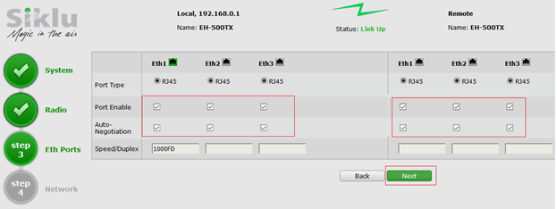
Step 5: (Quick Config Step 3 - Ethernet Ports)
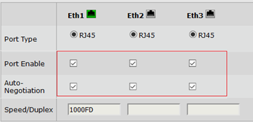
In this tab, we generally do not need to make any changes. This tab does give us the option to make changes to the Ethernet ports. We can disable ports and adjust the Negotiation parameters of the ports. Exercise caution when making changes to these settings as this could lead to loss of connectivity to the unit.
Click next to proceed.
Step 6: (Quick Config Step 4 - Network)
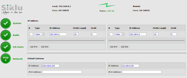
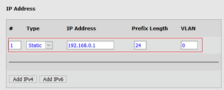
In this tab, we can assign IP addresses (static or DHCP, IPv4 or IPv6) and SNMP attributes to the Local and Remote units. In this example, the Local Unit (Master) will be 192.168.0.1 and the Remote Unit (Slave) will be 192.168.0.2. The default gateway is 192.168.0.254.
Once we have made the required changes we can click on the Apply button. Note that these settings are applied to the units (running configuration), these changes will take effect immediately however should the unit(s) be reset either hard reset (loss of power) or by the software (WebGUI) these settings will be lost.
Step 7: (Login using New WebGUI Credentials)
Make the necessary changes to your Network Interface and then navigate to the new IP address assigned to the unit if changed from the default 192.168.0.1, remember to use "https://" before the IP Address. Using the default Username and Password to access the Web GUI.
Step 8: Verifying Link Configurations
Check that your units are now showing the new Names and that the Status is showing "Link Up"
You will also need to confirm the Frequency is as configured.
Step 9: Committing Configuration
Now we will need to commit the changes. (startup configuration)
Click the "Save Remote Configuration" button and confirm the save, then click on the "Reboot Remote" button. The remote unit will then restart.
Now click the "Save Local Configuration" button and then click on the "Reboot Local" button. The Local unit will then reset. (At this time there is a bug in the WebGUI where it is displaying "Reboot Remote" on the local configuration tab).
Step 10: Confirm Link
After a short time, your units will restart and re-establish a Link using the saved configurations.
Log into the Local Unit WebGUI and confirm you have a "Link Up" Status
