cnWave - PtP Basic Link - Legacy
Description: cnWave V1000 Point to Point Link
Step 1: Login
Login to the WebGUI - https://169.254.1.1
Default Login Credentials
Username: admin
Password: admin
Step 2: Dashboard
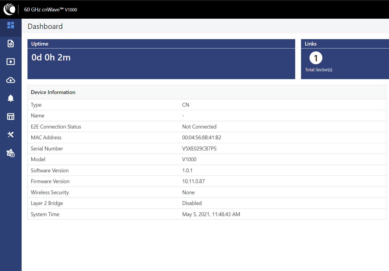
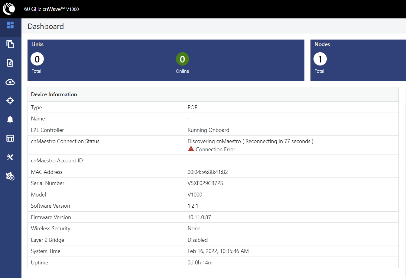
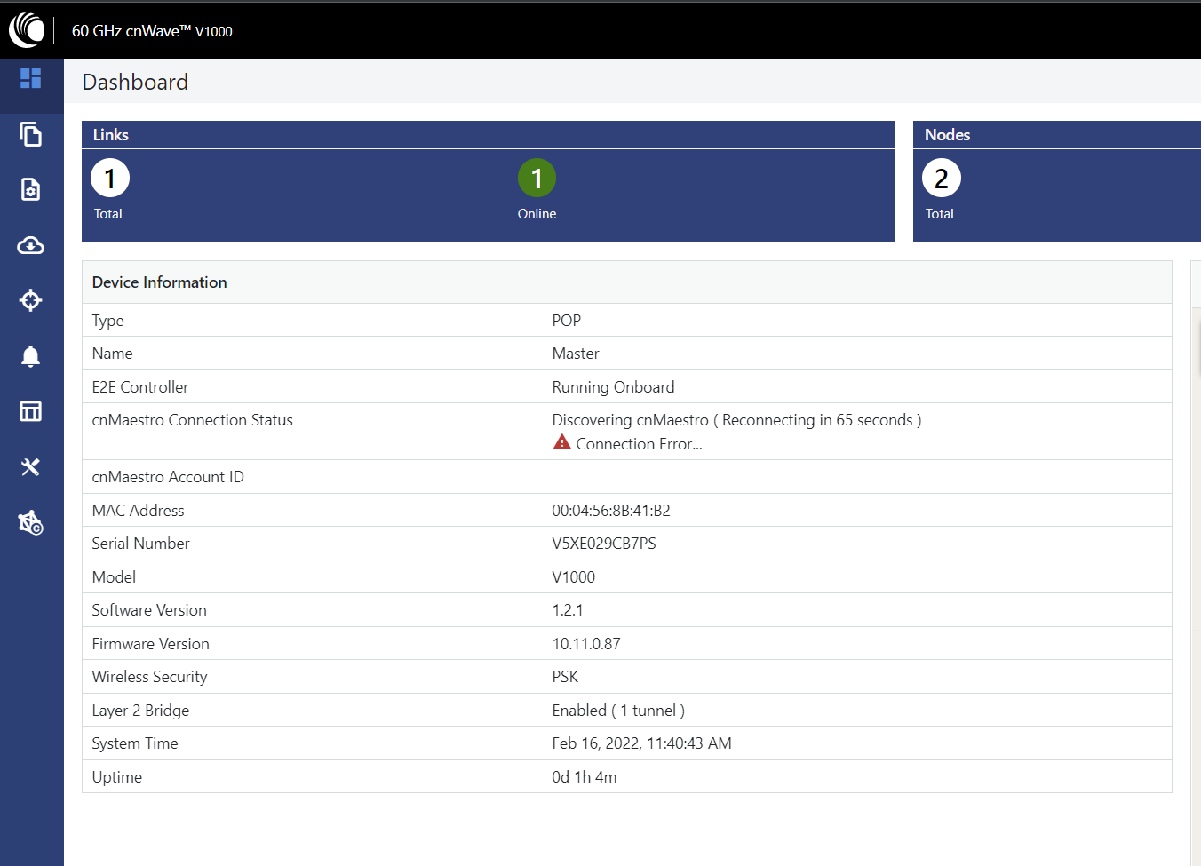
Here were can note the MAC Address, Serial Number and Software Version
Step 3: Configurations- Network
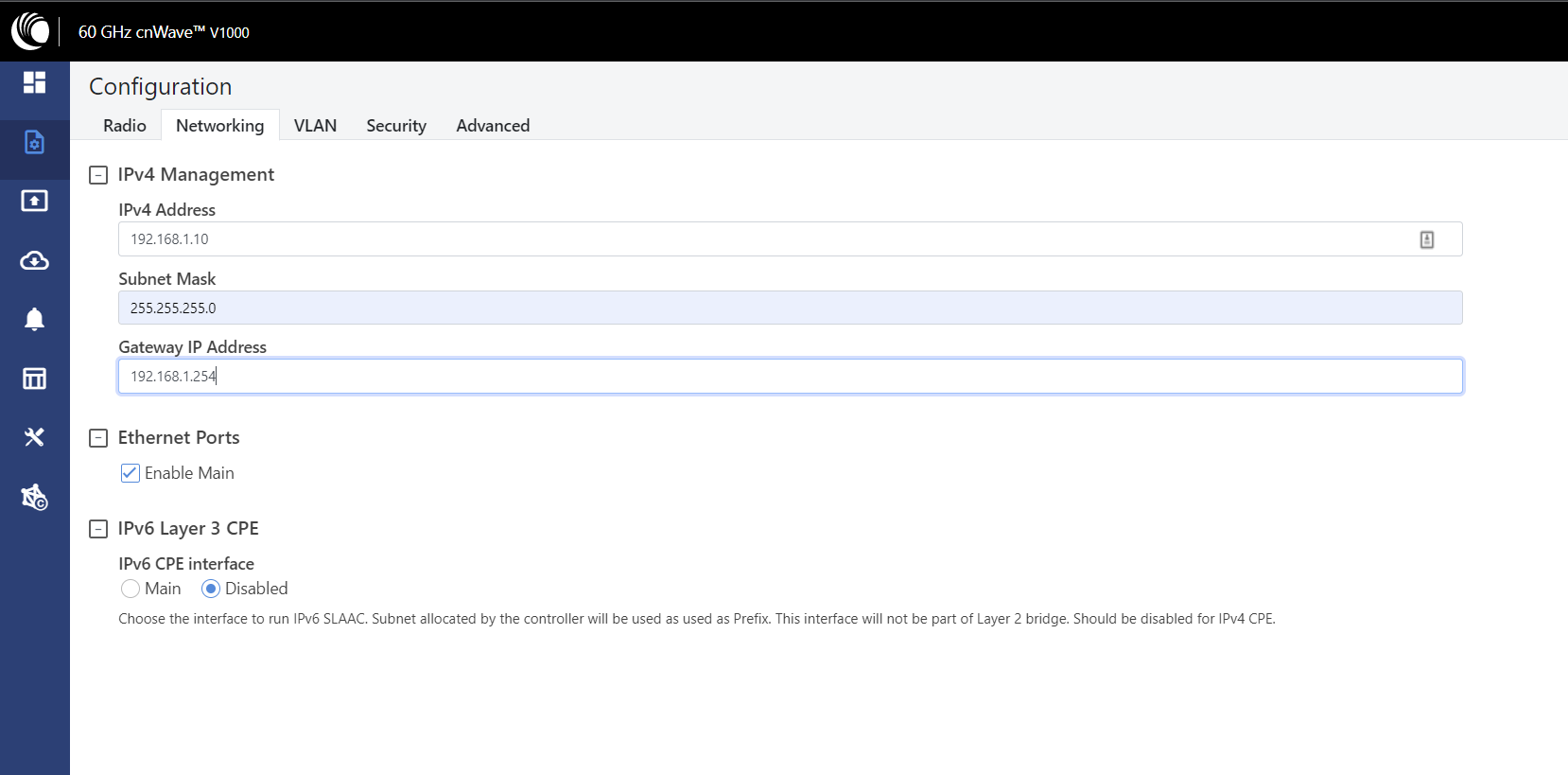
Configure the IP Address, Subnet Mask and Default Gateway as required and select Submit
Re-login using the new IP Address - in our example https://192.168.1.10
Step 4: Enable E2E Controller
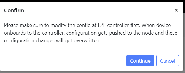
Navigate to Onboard E2E Controller and select Enable.
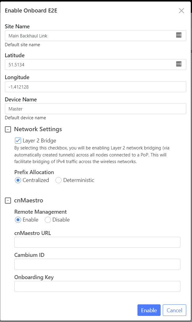
Complete the Enable Onboard E2E Settings - Site Name, Latitude, Longitude, Device Name and Remote Management (cnMaestro) where required.
Note: The unit will reboot once the E2E Controller has been enabled
Login and note the New Dashboard - E2E Controller Enabled
Step 5: Topology - Add Sites
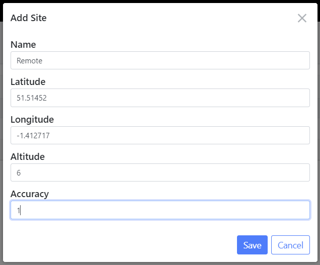
Select Add New to create a new site
Complete the fields Name, Latitude, Longitude, Altitude and Accuracy as per site location, then save
Step 6: Topology - Add Nodes
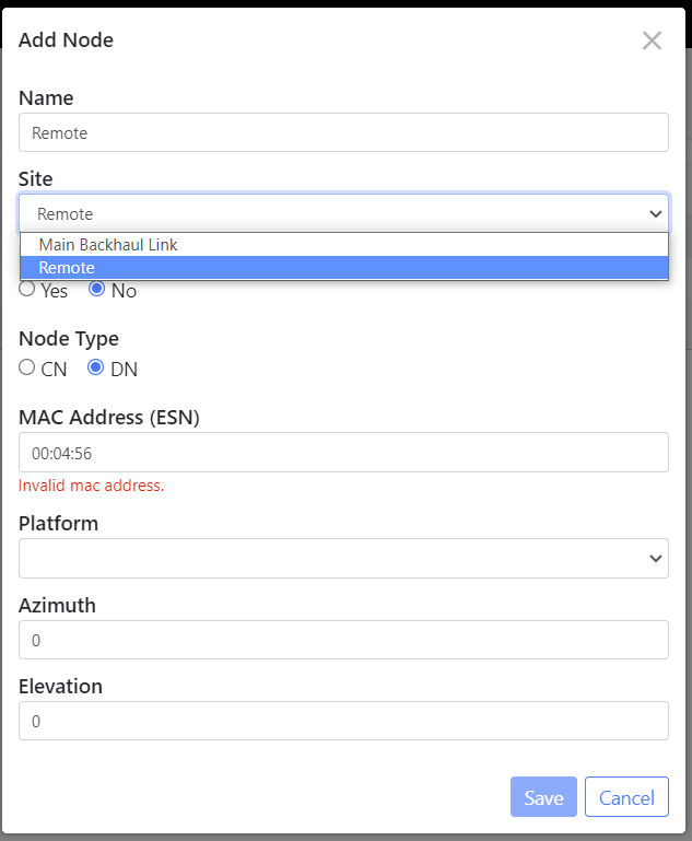
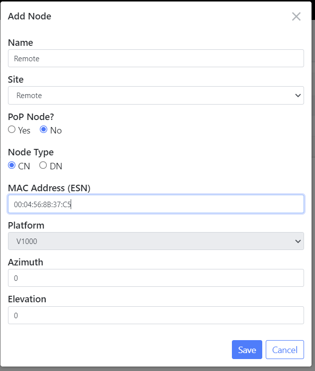
Select Add New and complete the following steps
Name and Select the Site
Node Type (CN) and MAC Address - Remote Unit
Node added, but will show offline until a link is created
Step 7: Topology - Add Link
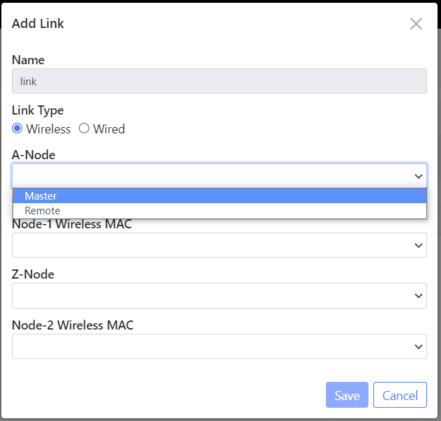
Currently no links are configured, select Add New
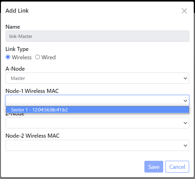
Select Link Type Wireless, then select the A-Node Site in our example this will be Master
Select the A-Node Sector
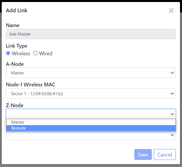
Select the Z-Node in our example this will be Remote
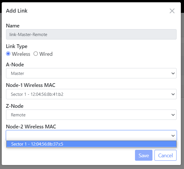
Select the Z-Node Sector, then click Save
Link Configured showing offline
Once the units are aligned we should see the Link change to active
We can also note the Topology - Nodes page will show the unit details.
Please allow 3 - 5mins for the remote unit to save the current configurations and reboot
Note the firmware version is different to the master. Follow the Step 11 to update the firmware
Step 8: Network Settings
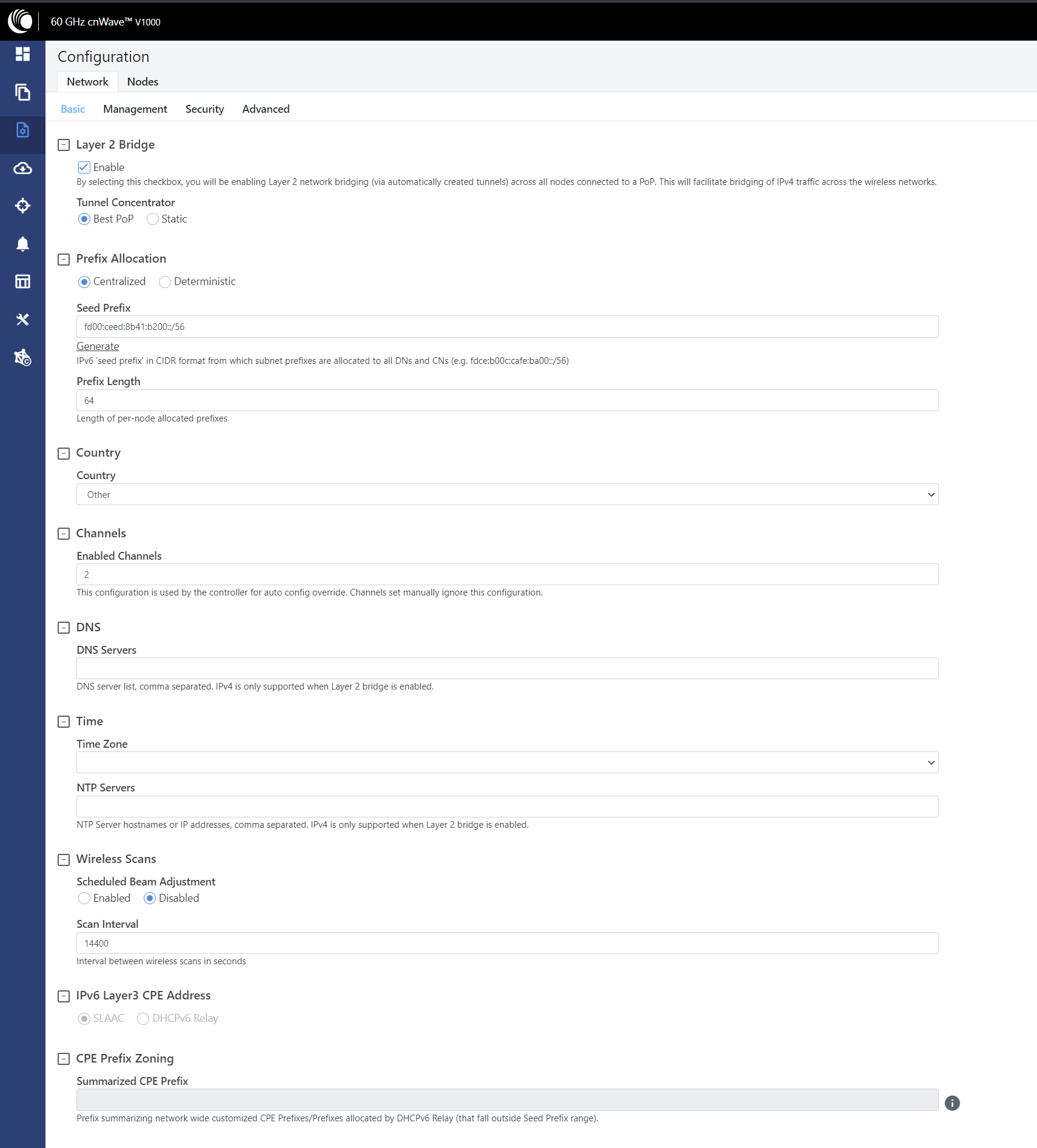
Navigate to Configuration - Network- Basic Tab
Set the Country and Time settings applicable to the site location
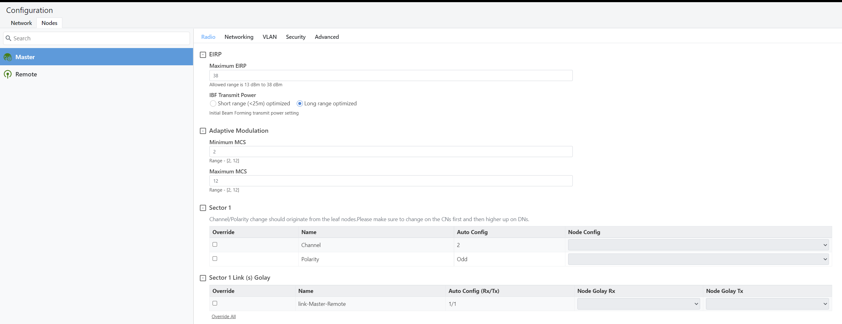
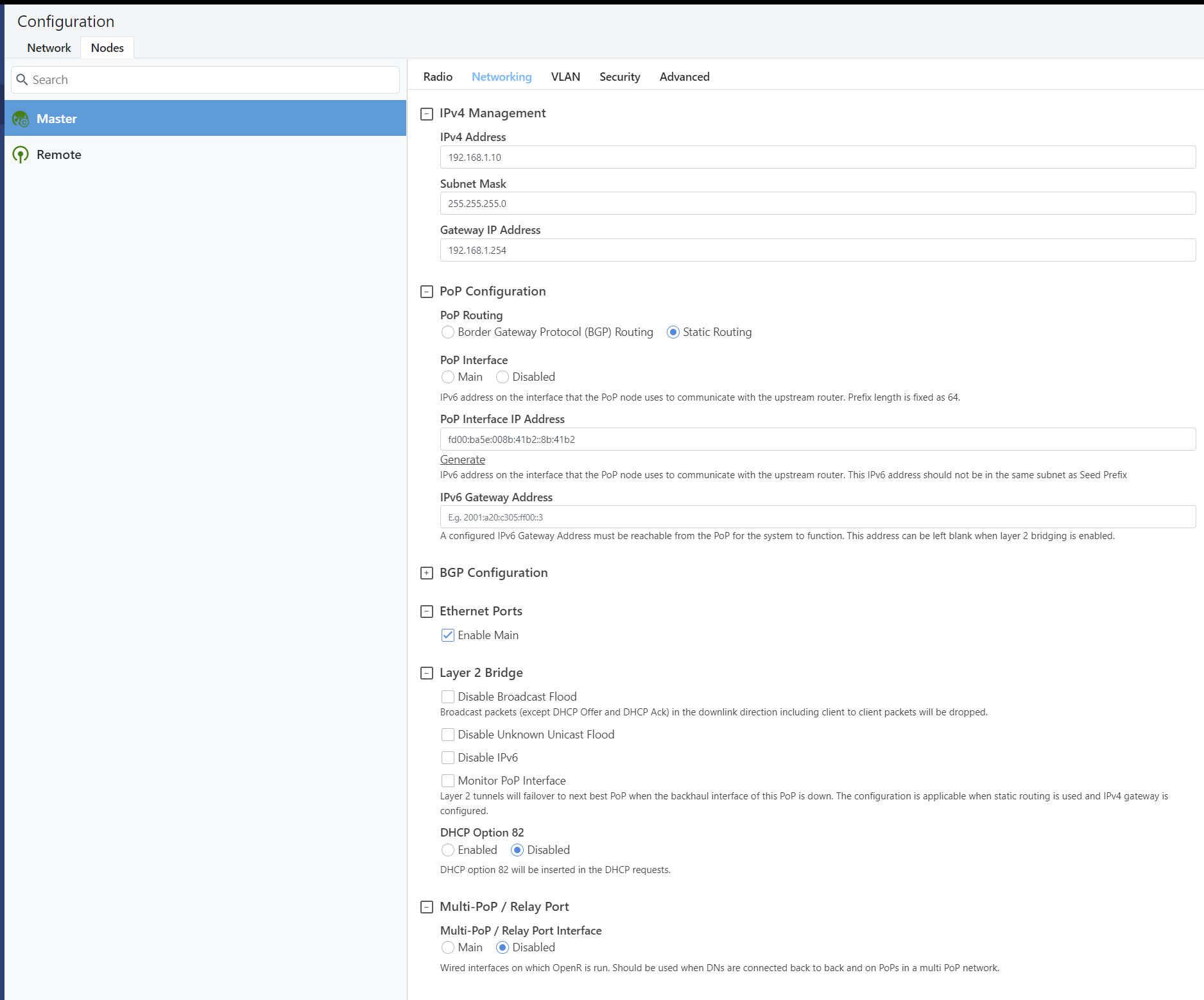
Navigate to the Configuration - Nodes Tab
Master Radio Settings - leave as automatic or adjust the Channel, Polarity & Golay as required
Master Network Settings - Confirm IP settings as per initial configuration. In our example the IP address 192.168.1.10 was configured.
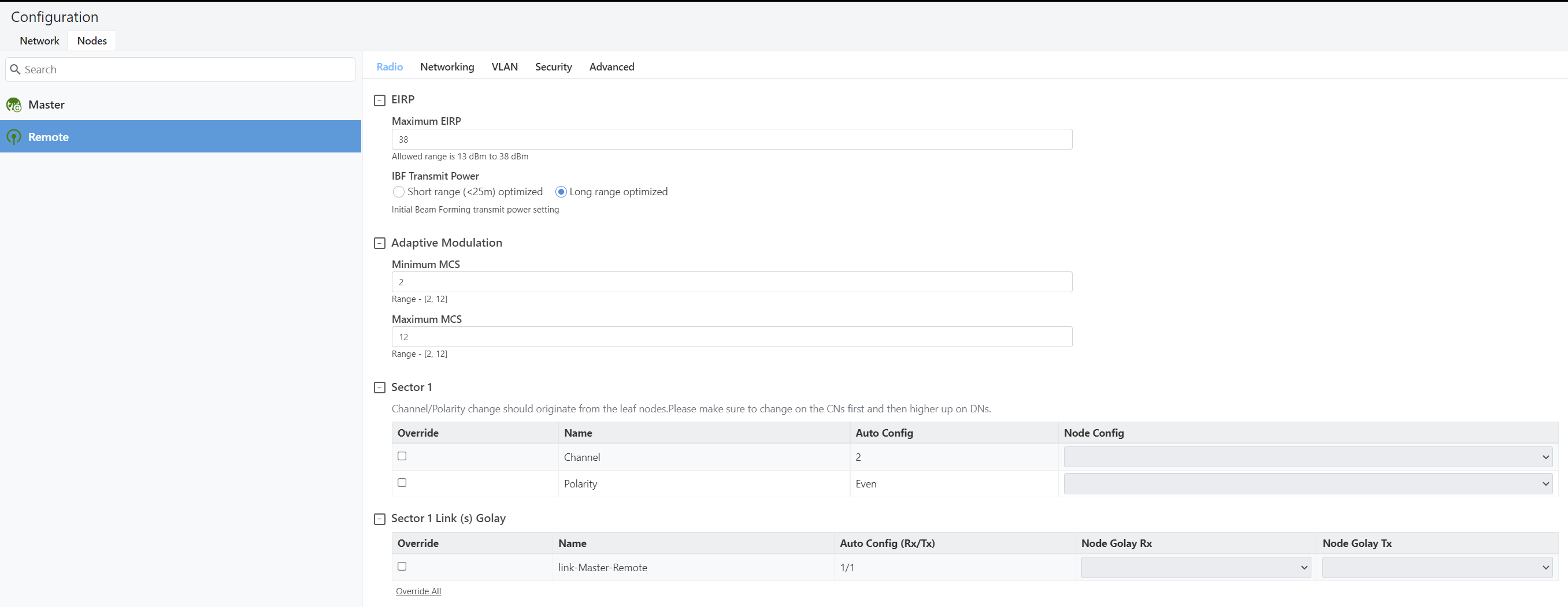
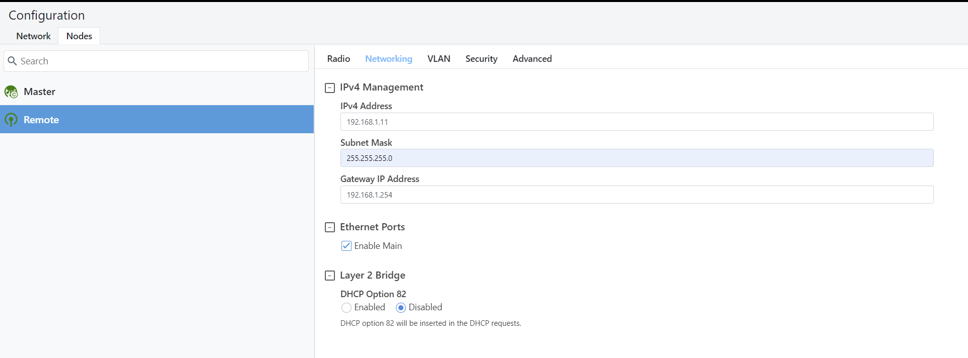
Navigate to the Configuration - Nodes Tab
Remote Radio settings - leave as automatic or adjust the Channel, Polarity & Golay as required
Remote Network Settings - In our example we have configured 192.168.1.11
Note the remote device may drop the link and reboot as the new configuration will be uploaded by the E2E Controller. Allow up to 5 minutes for the link to re-establish.
Step 9: Configure Security
Navigate to Configuration - Nodes - Master - Security Tab
Here we will configure the Wireless Security. In our example we selected PSK and inserted a passphrase.
Note: the remote site will disconnect and reboot as the E2E Controller will upload the new configuration.
Step 10: Confirm Link Status - Dashboard
Navigate back to the Dashboard and confirm the Links are online and the Wireless Security shows PSK.
Step 11: Remote Device Firmware Upgrade
Navigate to the Software Upgrade Tab - Note the Remote Image Version in our case 1.0.1
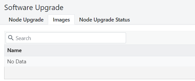
Navigate to the Images Tab - Then select Upload Image
Select the relevant image - for this example we are selecting the V1000 image V1.2.1
Once uploaded we will see the image available.
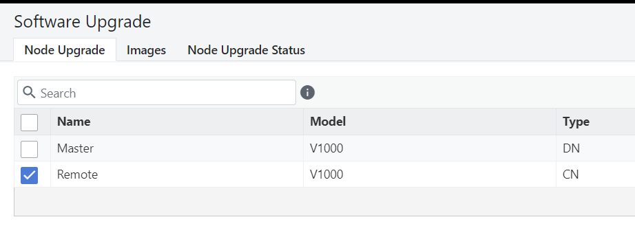
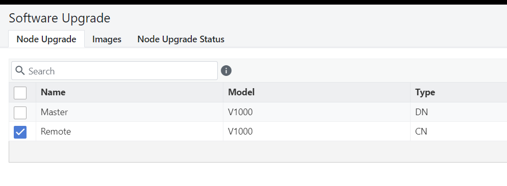
Navigate back to the Node Upgrade Tab - Select the device to upgrade - we have selected Remote
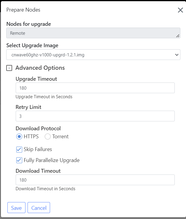
Click the Prepare button, confirm the advanced Options as per preference, click Save.
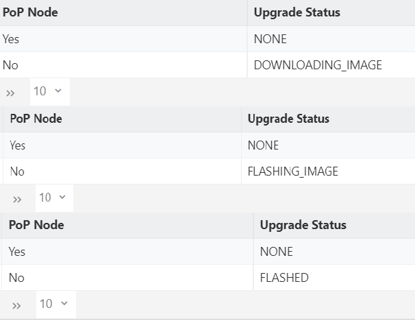
Await the Flashing process - Image Downloading, Image Flashing until we see Flashed
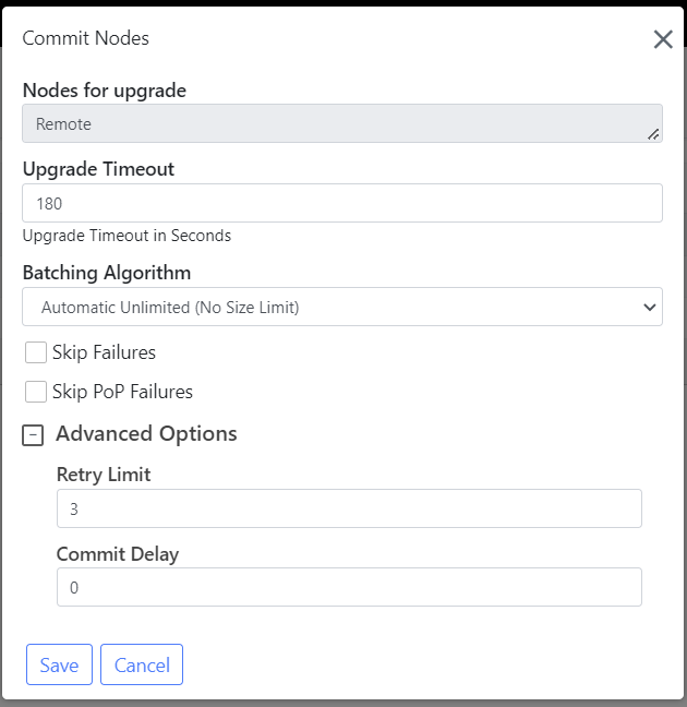
Select the Remote again and select Commit, confirm settings and save
Note the remote device will be offline for up to 10 minutes while the unit reboots up to two times.
Confirm the link has re-established after the upgrade
