Siklu Multihaul TG - Quick Start Guide
Siklu MultiHaul TG – PtMP Basic Setup
Step 1 – Login
Step 2 – Firmware update * Optional
Step 3 MH-N366 Node Config
Step 4 Configure the Terminal Unit - CN
Step 5 – Checking the Status
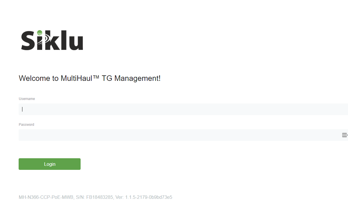
Step 1 – Login
The default IP address of the unit (for both Web-GUI and CLI) is 192.168.0.1
The default login credentials are “admin” for both the username and password.
To connect to the Web-GUI enter https://192.168.0.1 on your internet browser.
Step 2 – Firmware update * Optional
Confirm the current running Firmware version and update where necessary.
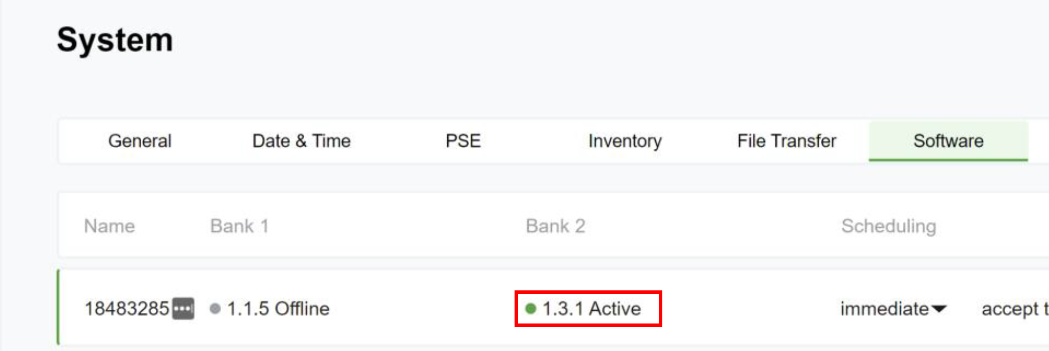
System > Software
In our example we are running Firmware Version 1.1.5 with Version 1.1.0 in the secondary bank.
System>File Transfer
Select Choose a File and select the Firmware File to be applied
Click Upload
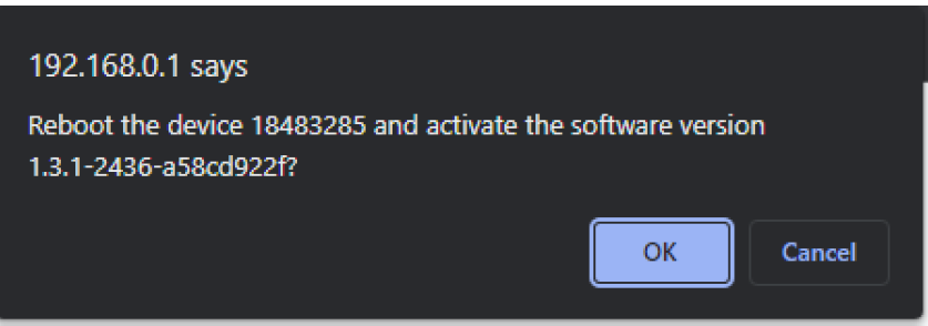
System>Software and select Run
Step 3 – MH-N366 Node Configuration
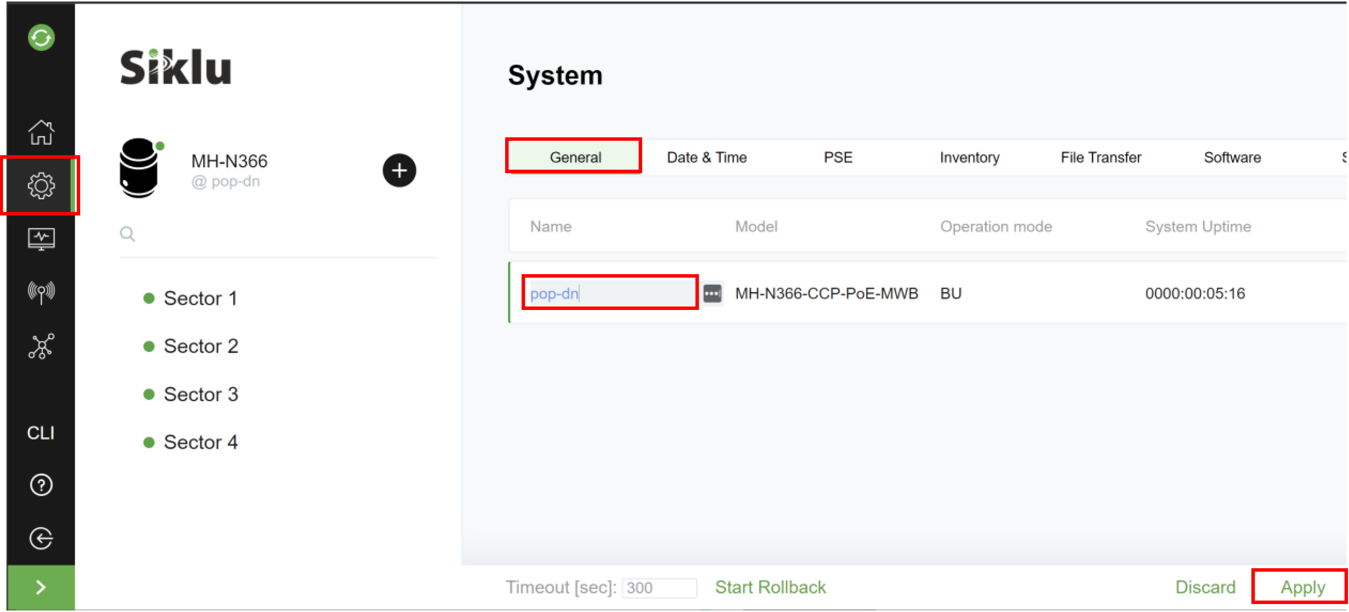
1. Set system name:
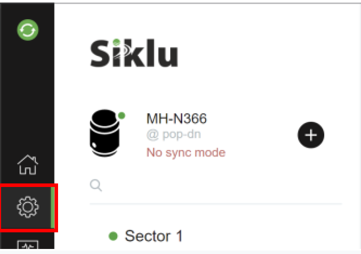
System>General
Note: changing system name is optional and requires reboot to take effect.
2. Set node as pop-dn (POP Node = enabled):
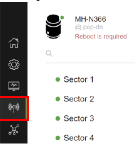
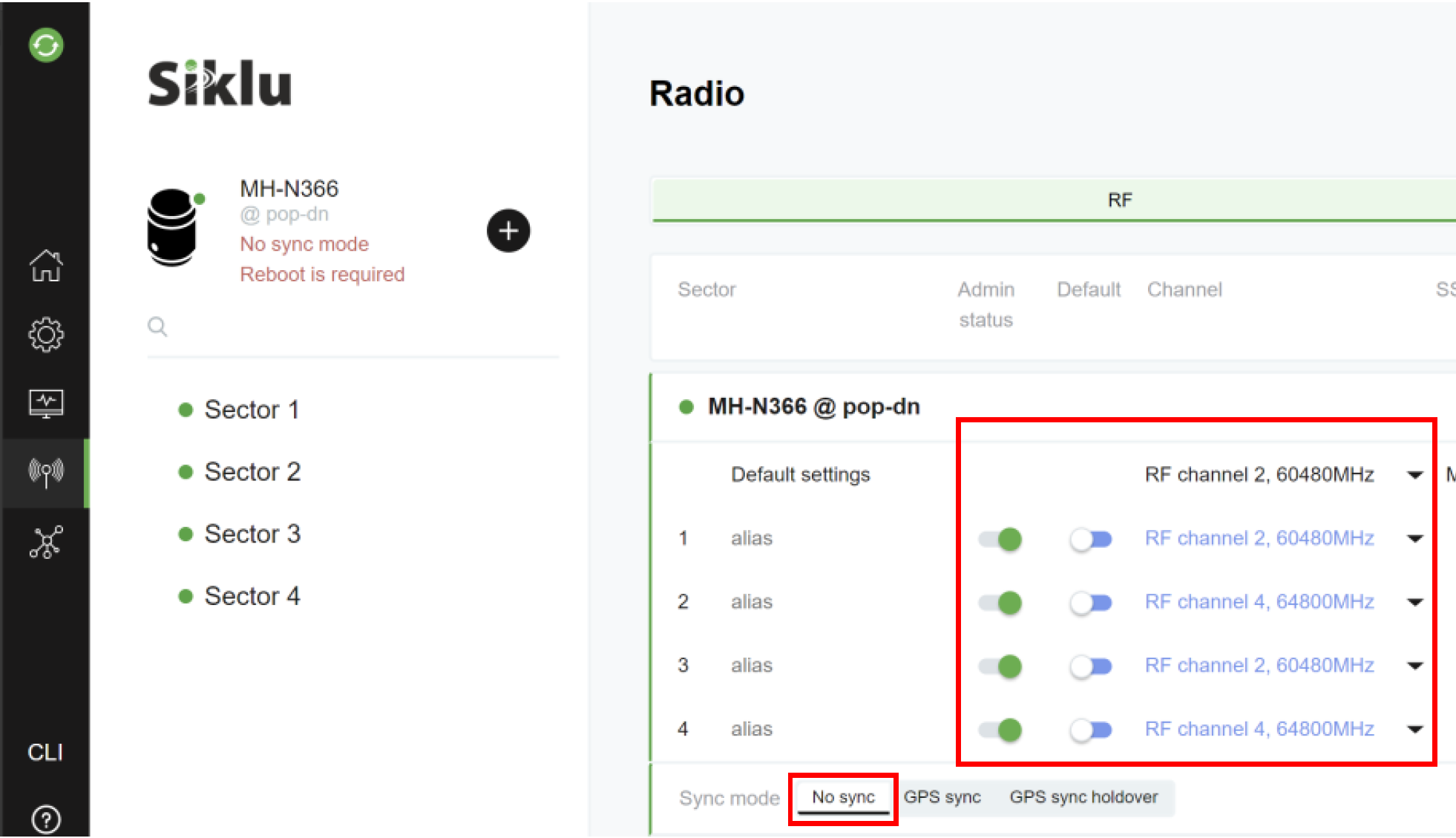
Radio > RF
3. Change frequency (ch2->ch4) on sectors 2 and 4 (leave sectors 1&3 on default ch2):
It is recommended to disable any sectors that will not be used in your deployment.
GPS
GPS signal is used to synchronize the transmission of nodes and sectors within a node.
All N366 nodes must be in locked GPS state for links to initialize (no GPS signal is required on terminal units or for PTP links).
If a node is without a locked GPS signal, it will not be able to ignite links or maintain links after a short period of time.
It is recommended to set the N366 Sync Mode to No Sync whilst testing indoors with no GPS signal.
Remember to set GPS Sync before deploying the N366 on-site.
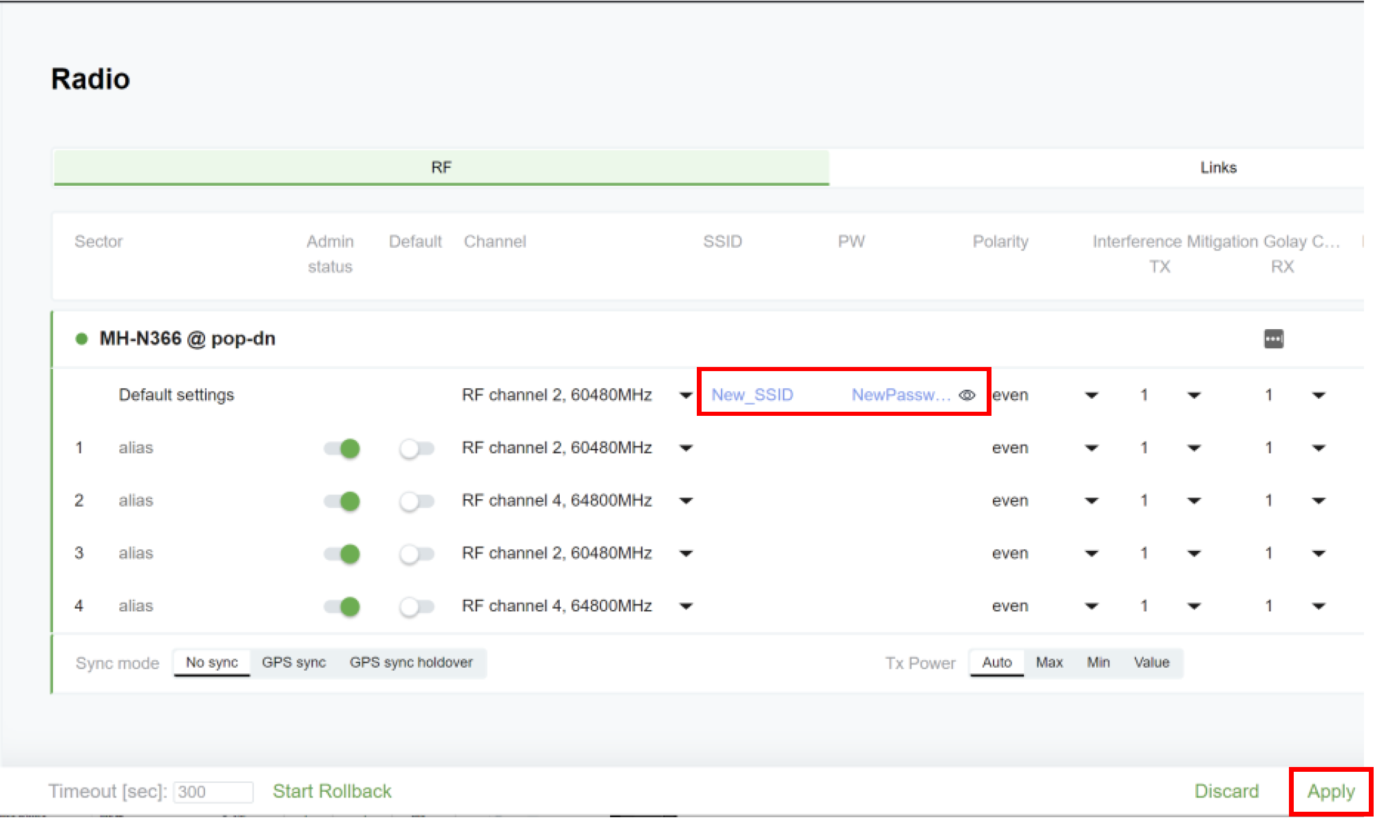
4. Change SSID & Password (optional) Default MultiHaul / MultiHaul
Once you have entered your desired SSID and Password click Apply.
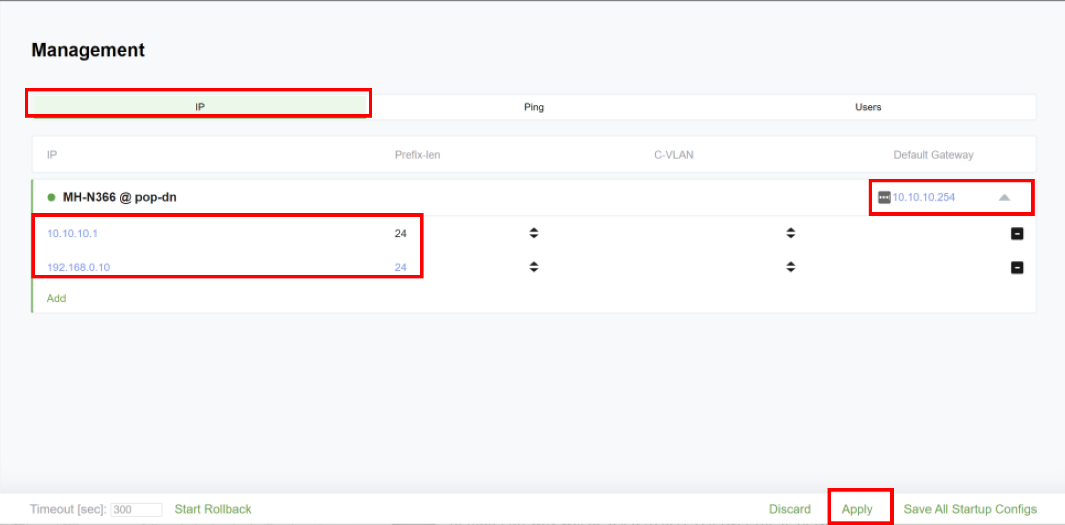
5. Set IP Address and default gateway:
Management > IP
You can define multiple IPv4 addresses (4)
If you change the IP address from the default 192.168.0.1 and apply you will need to re-login using the new defined IP address. In our example we could use 192.168.0.10 or 10.10.10.1
You can add management VLAN if required
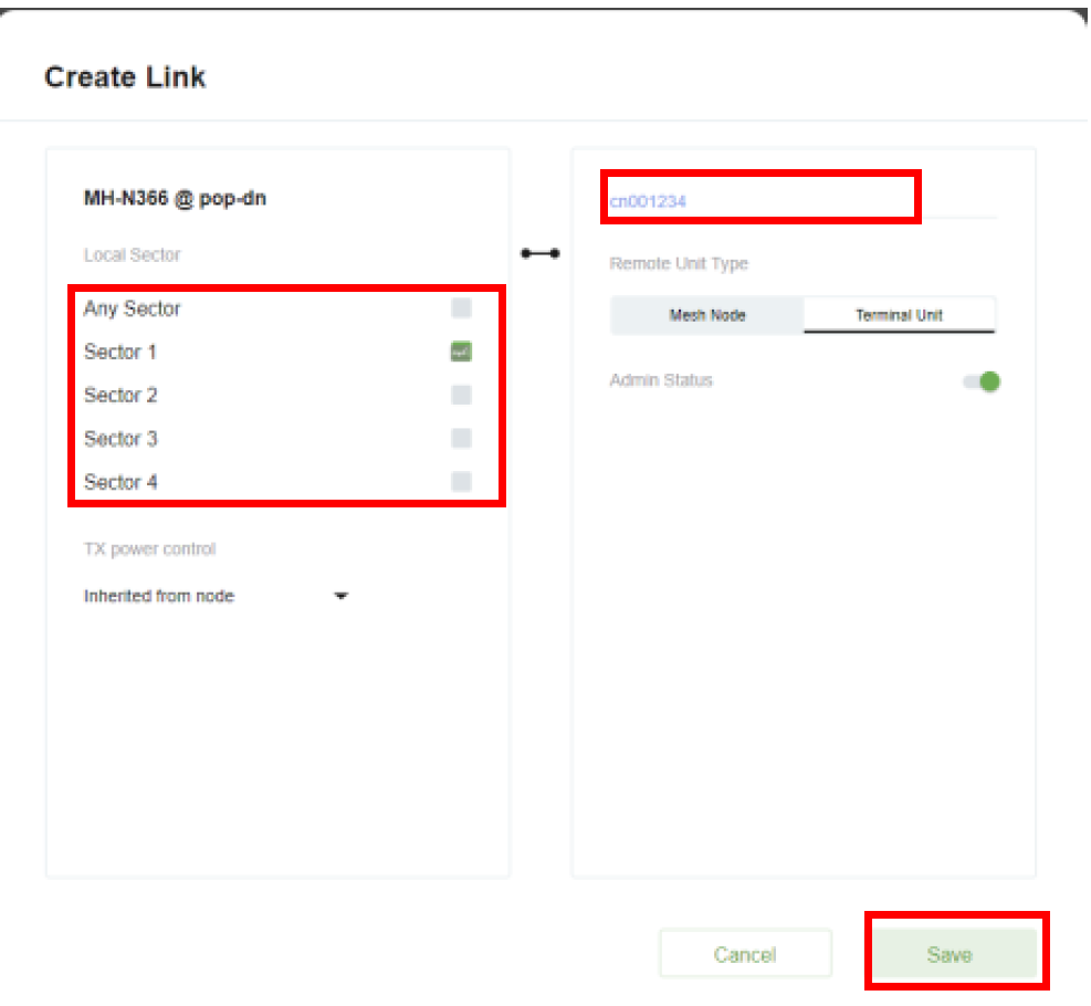
6. Configure links
Radio>
Give the Terminal Unit a name in our example we have used “cn001234”, we have selected sector 1 as this will be the sector, we expect the Terminal Unit will be connected to.
Click save
Alternatively, if known, you may use the last 8 digits of the TU serial number, this is the default name of the TU. In this case, no local configuration is needed on the TU (MH-T260/T265/T280) – all further configurations will be done via the N366 DN.
If you are not sure what sector of the node faces the terminal unit, you may select more than one sector
Note:
If you configure the link on more than one sector, the node will try to ignite links using
the different sectors configured. There is no guarantee that the node will select the optimal
sector. It is NOT RECOMMENDED to leave links configured one more than one sector!
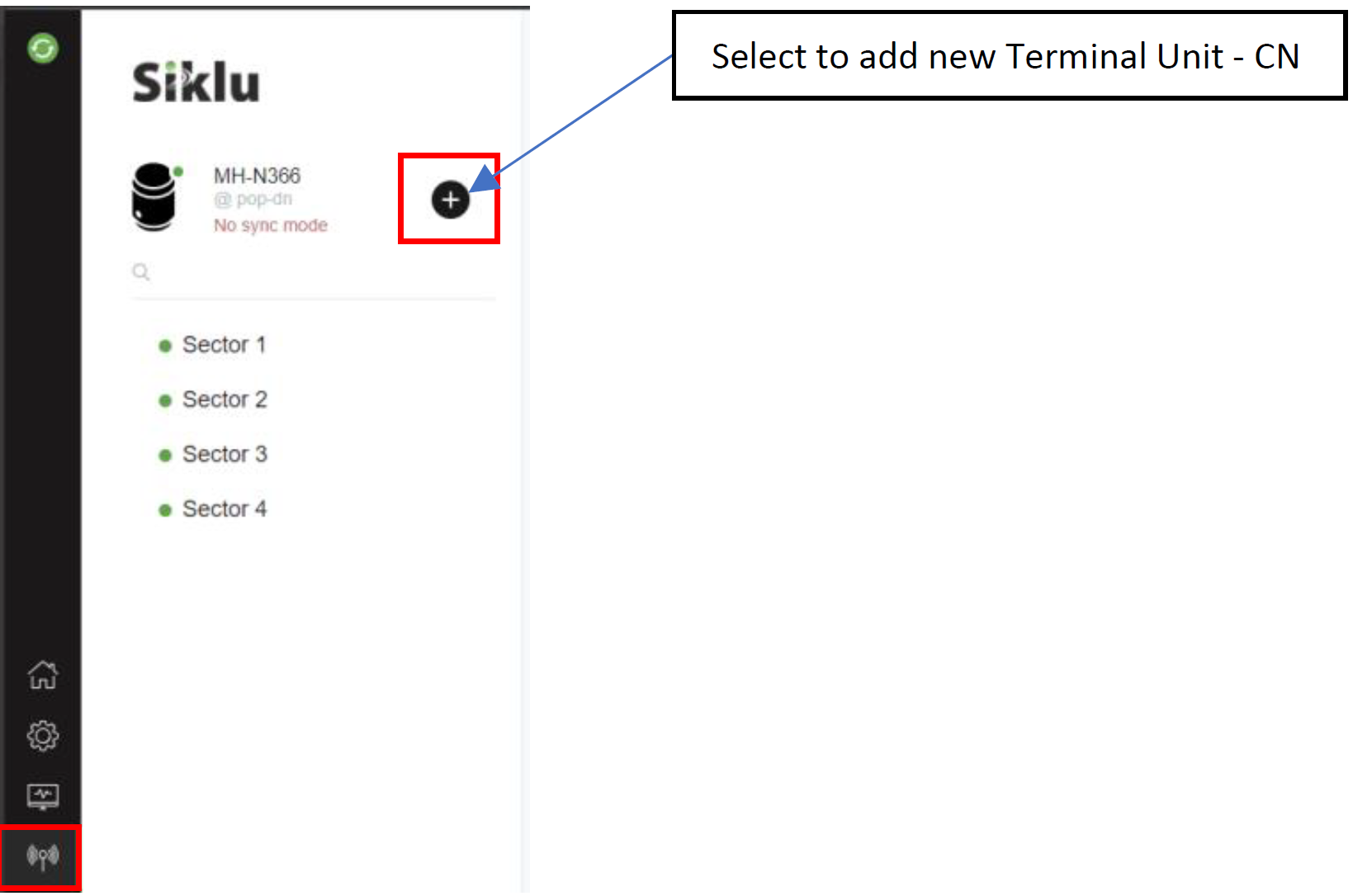
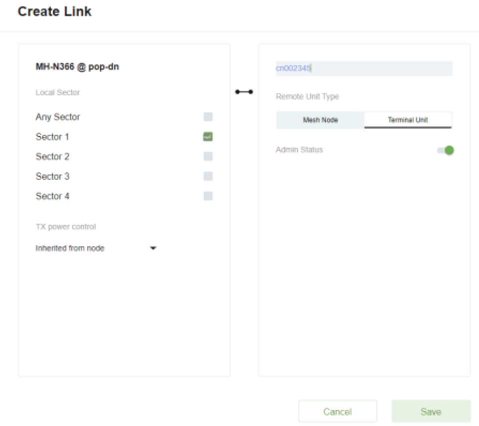
7. Repeat step 6 for additional TUs you may be connecting to this node (in our example: cn002345).
Select to add new Terminal Unit - CN
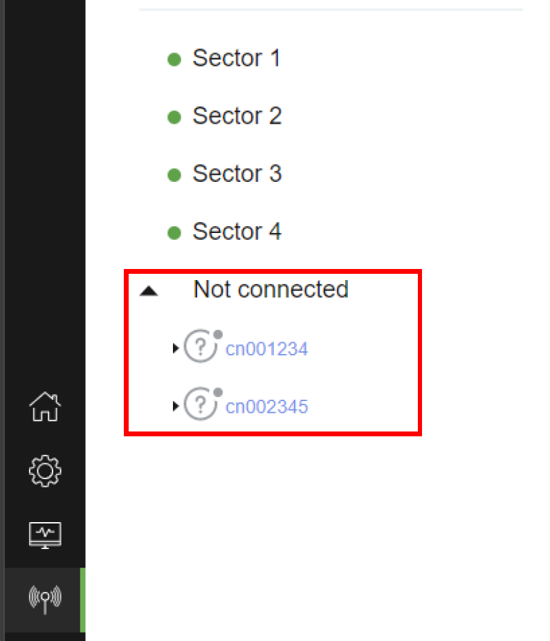
We can see the links configured but not active (Not connected):
8. Commit changes
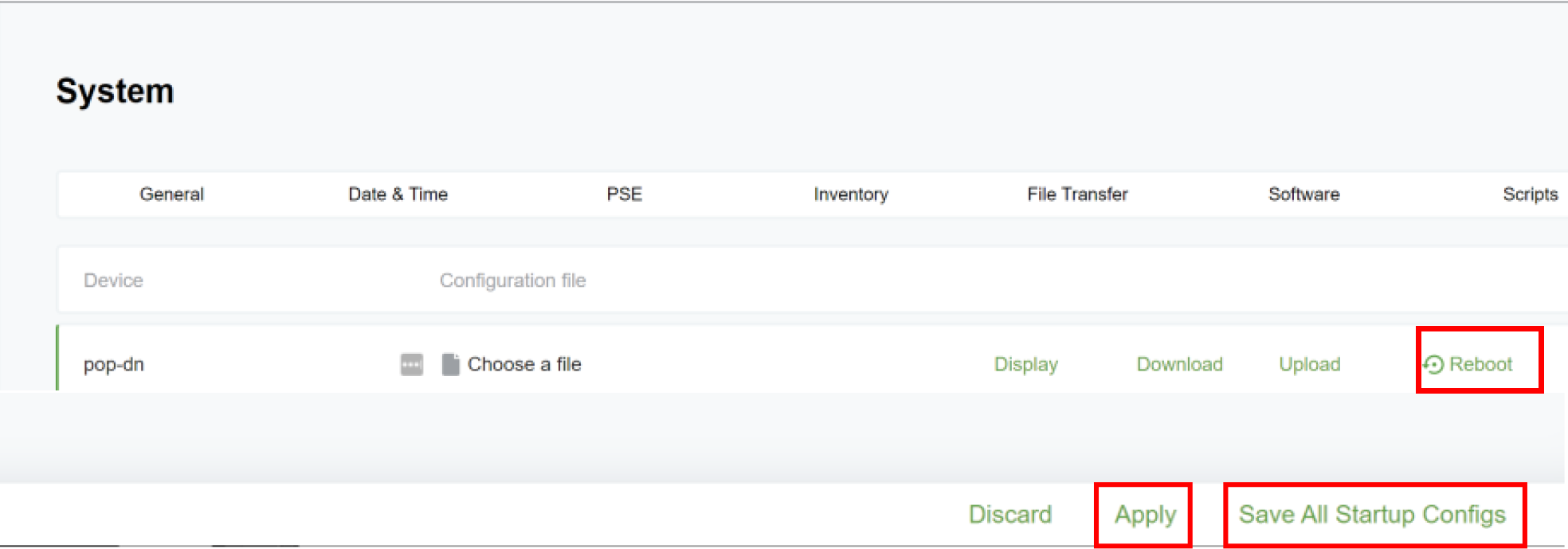
System> Device Config
Click Apply then Save All Startup Configs and then reboot for changes to take effect.
Step 4 Configure the Terminal Unit - CN
1. Set system name:
If you prefer to manage the TU using its default name (last 8 digits of its serial number), you may skip this step. No further configuration is needed.
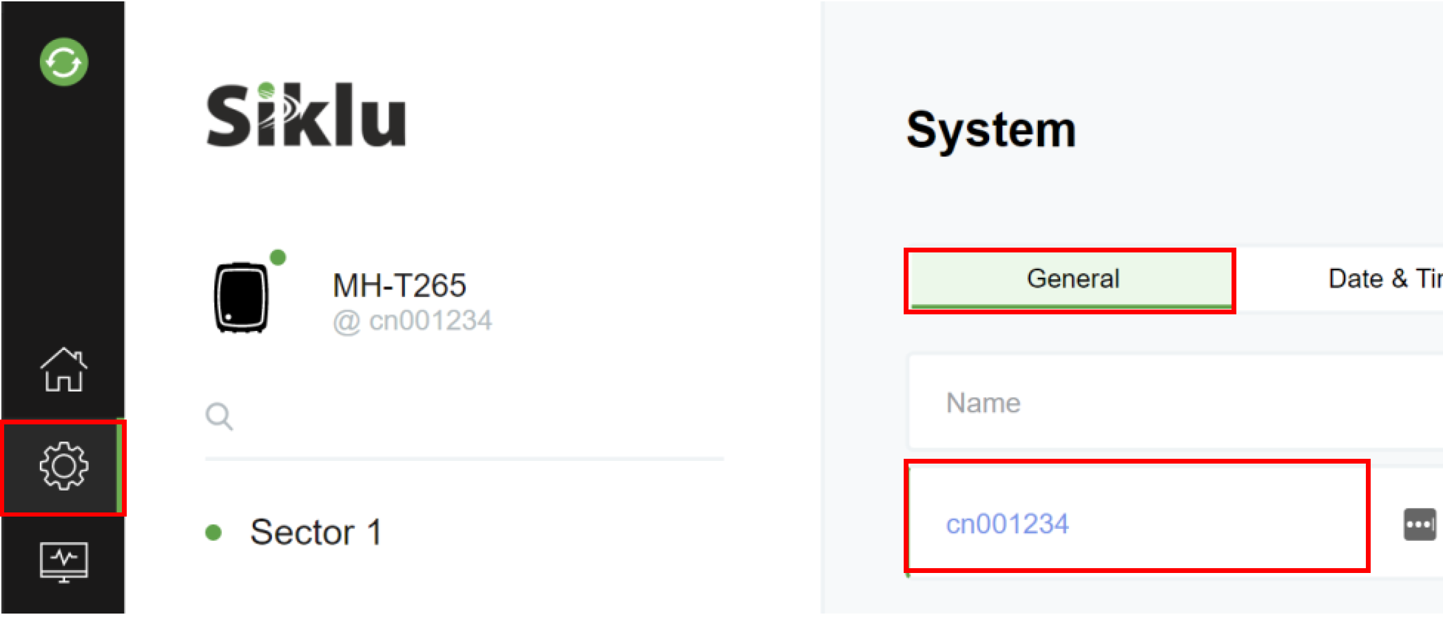
If you prefer to manage the TU using a defined name, set the name here System>General
Click Apply
2. Change SSID & Password (optional) Radio>RF
Click Apply
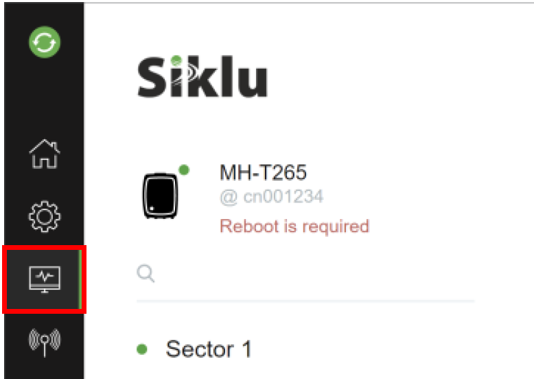
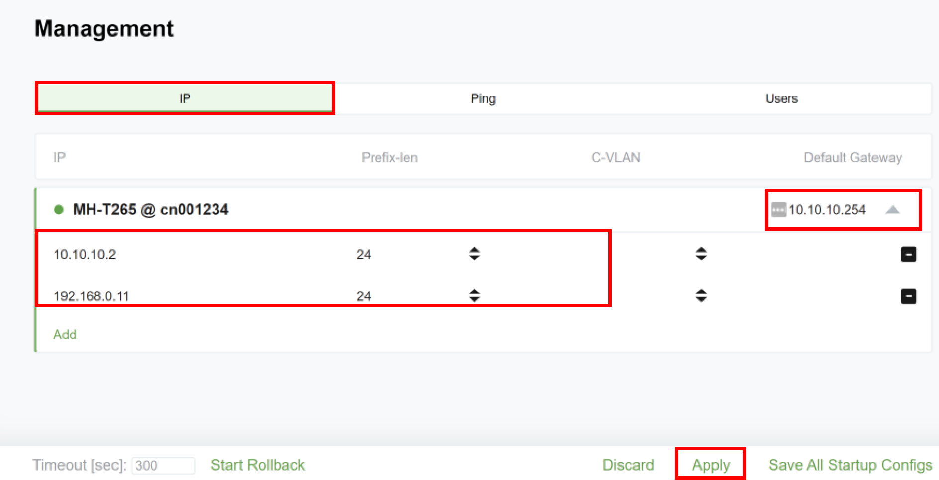
3. Set IP and default gateway: Management>IP
Click Apply
Note you will need to re-login using the new assigned IP address (10.10.10.2 or 192.168.0.11)
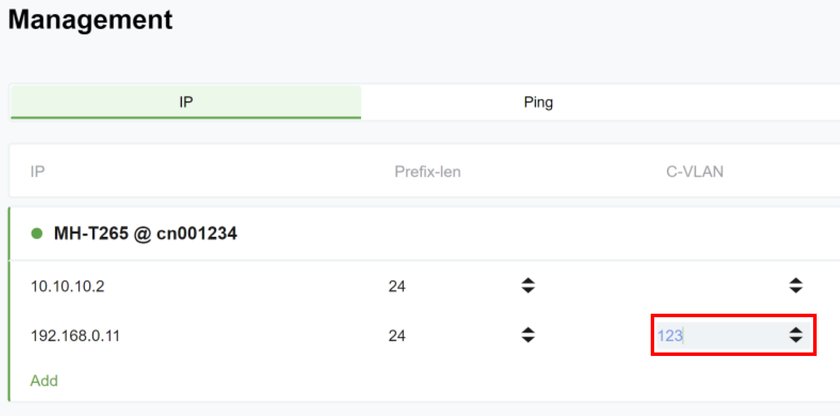
You may add management VLAN if required (under the C-VLAN section).
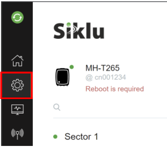
4. Commit changes
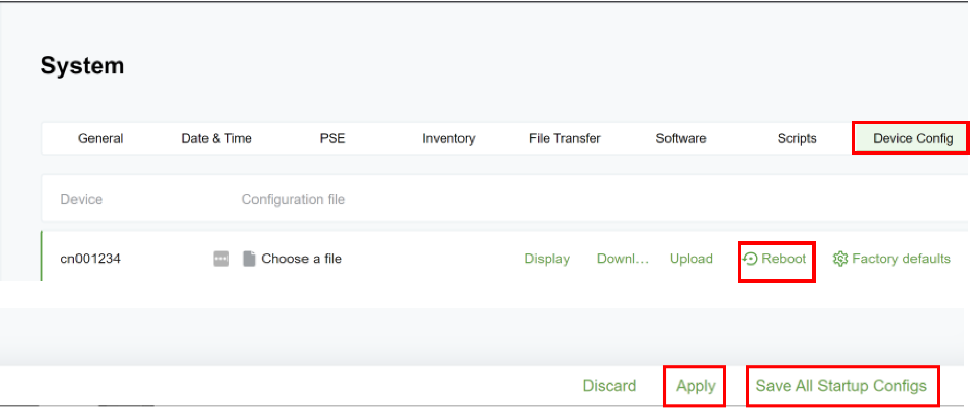
System>Device Config
Click Apply then Save All Startup Configs and then reboot for changes to take effect:
Step 5 – Checking the Status
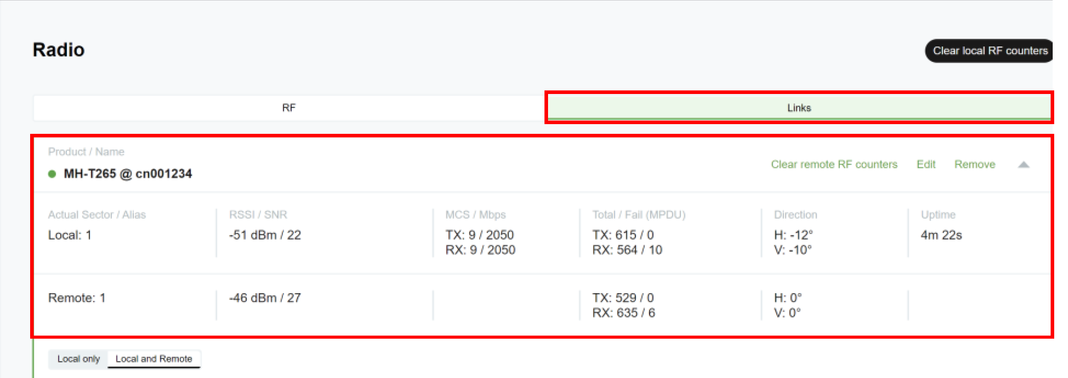
Terminal Unit: CN
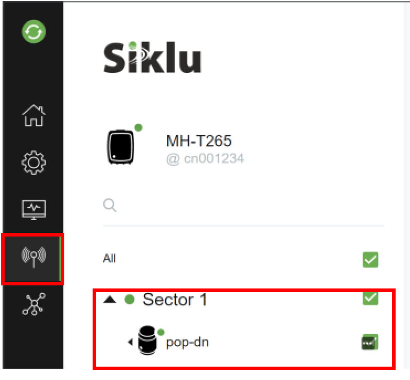
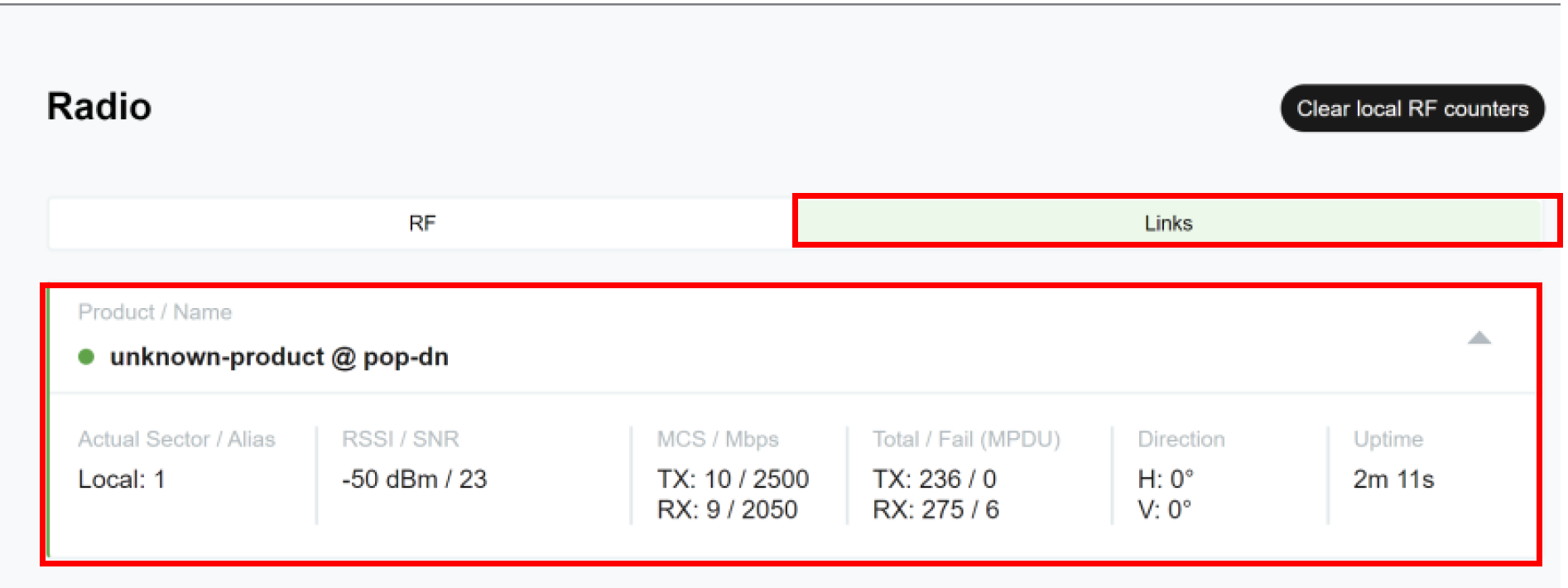
Radio>Sector 1>
Here you should see the DN is our example pop-dn
N366: DN
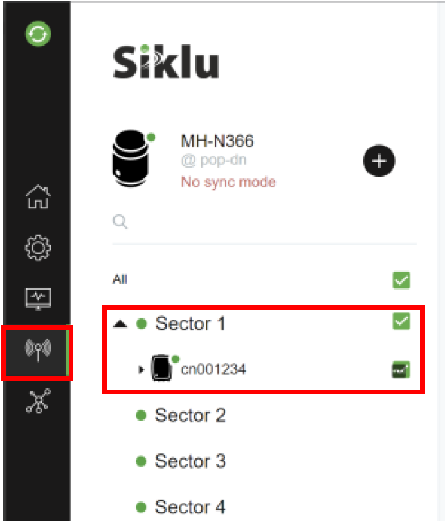
Radio>Sector1>
Select the Terminal in our example cn001234


