Cambium 450b PTP Configuration
Description:
Initial guide to creating a basic point-to-point transparent bridge link using two PMP 450b radios.
Method:
Master Radio Configuration
Step 1:
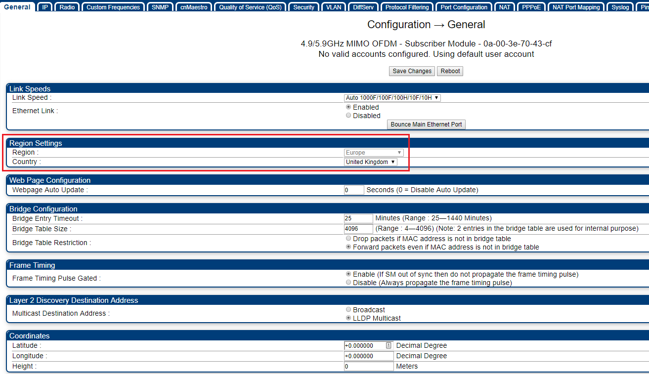
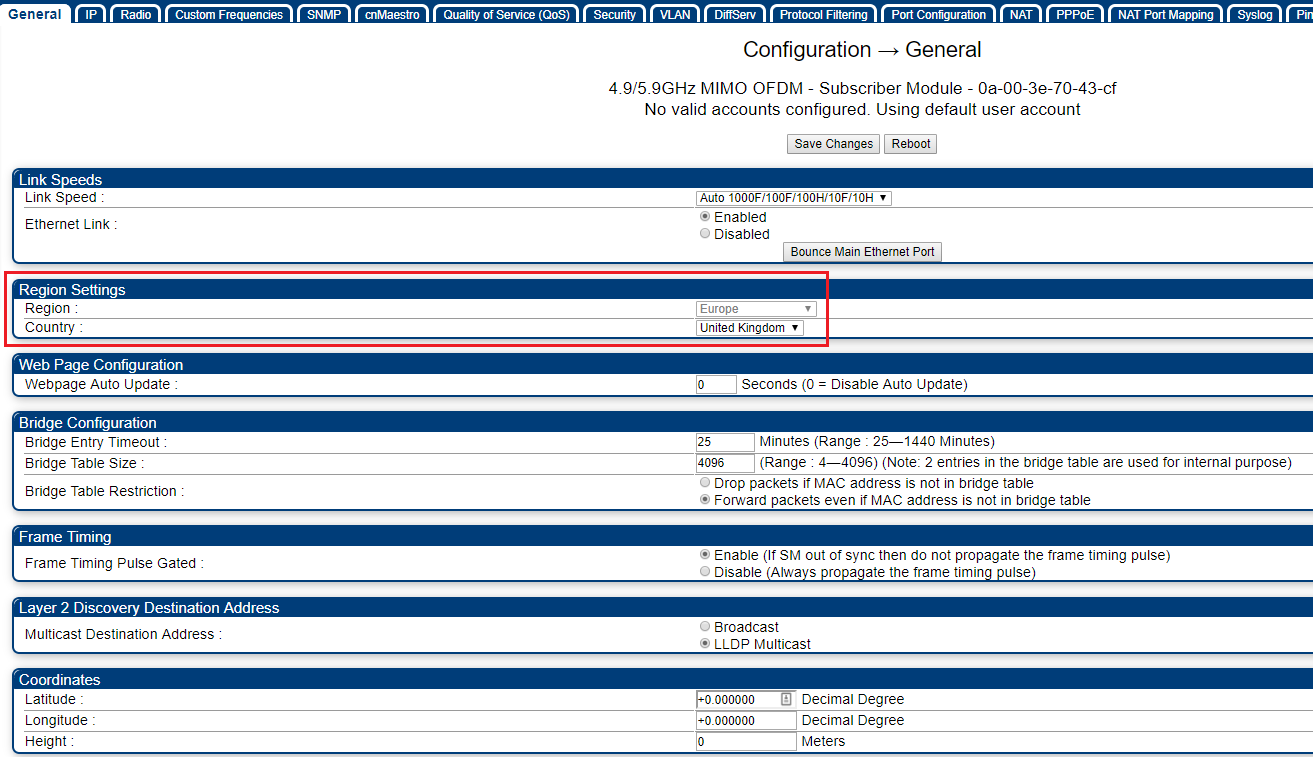
Under Configuration > General > Region Settings configure the region and country code (this should be the same on both master and slave radios):
Step 2:
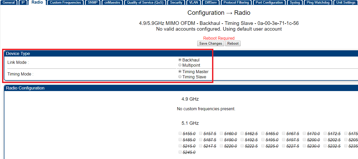
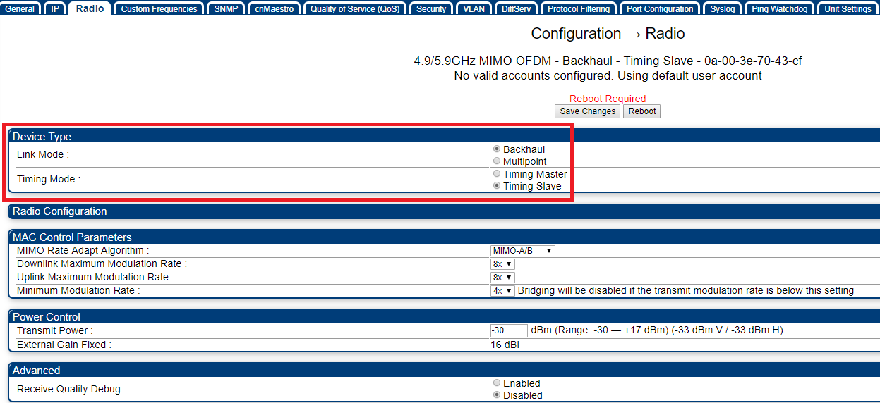
Under Configuration > Radio > Device Type configure the radio for Backhaul Mode. After saving the changes, configure the radio to be the Timing Master:
Step 3:
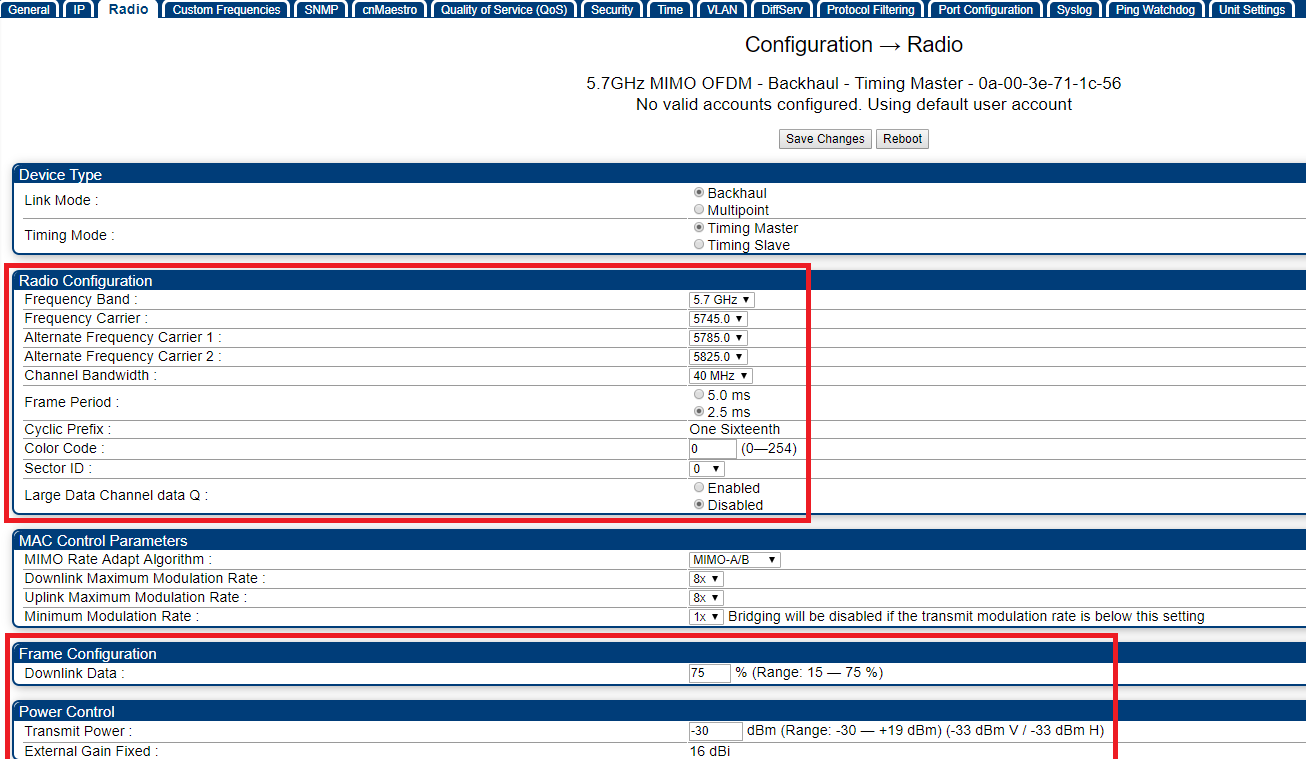
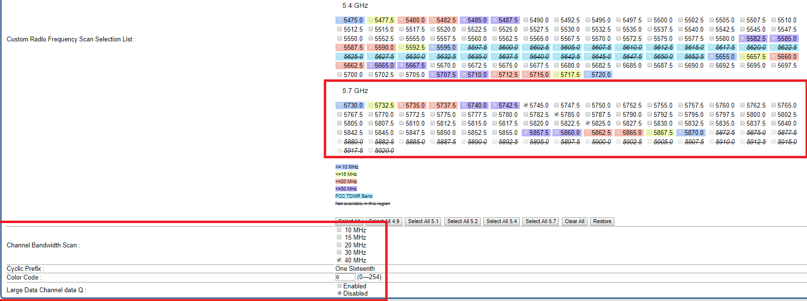
After performing a reboot, configure the desired radio frequencies, channel width, and colour code under Configuration > Radio > Radio Configuration, and configure the desired downlink ratio and transmit power under Configuration > Radio > Frame Ratio and Power Control:
NOTE: The transmit power and frequencies may require adjusting when deploying the link in the field as the RF environment will be different to that of the configuration bench.
Step 4:
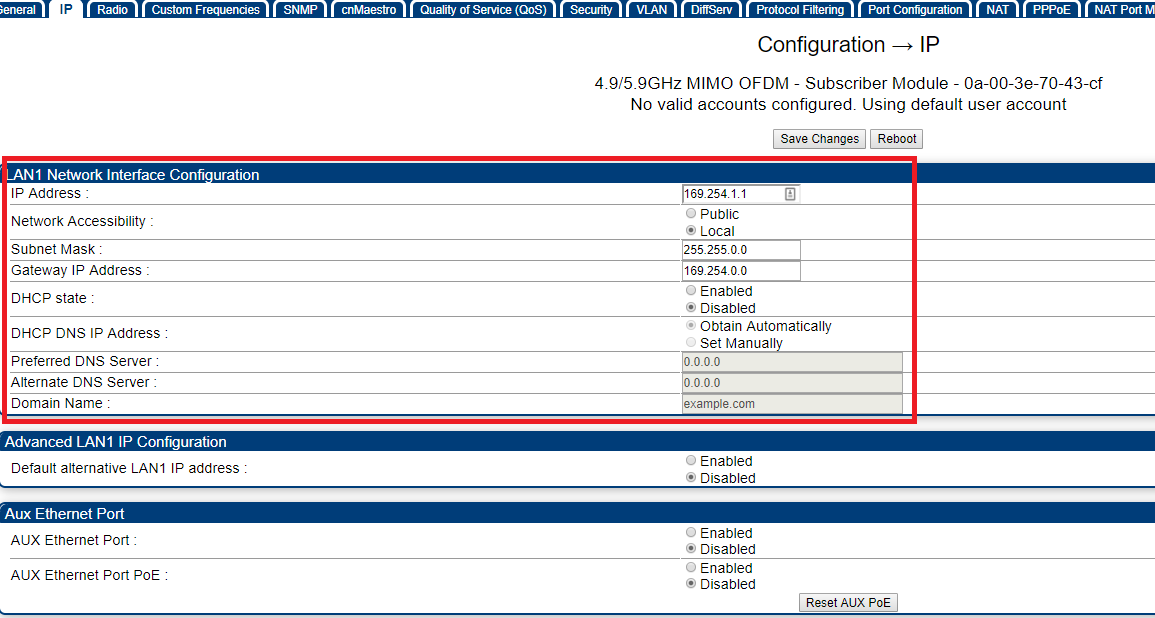
Under Configuration > IP > LAN1 Network Interface Configuration configure the desired IP address, subnet mask, and default gateway for the radio. DNS server IP addresses can also be set here:
Ensure you also Enable the default alternative LAN1 IP Address
Step 5:
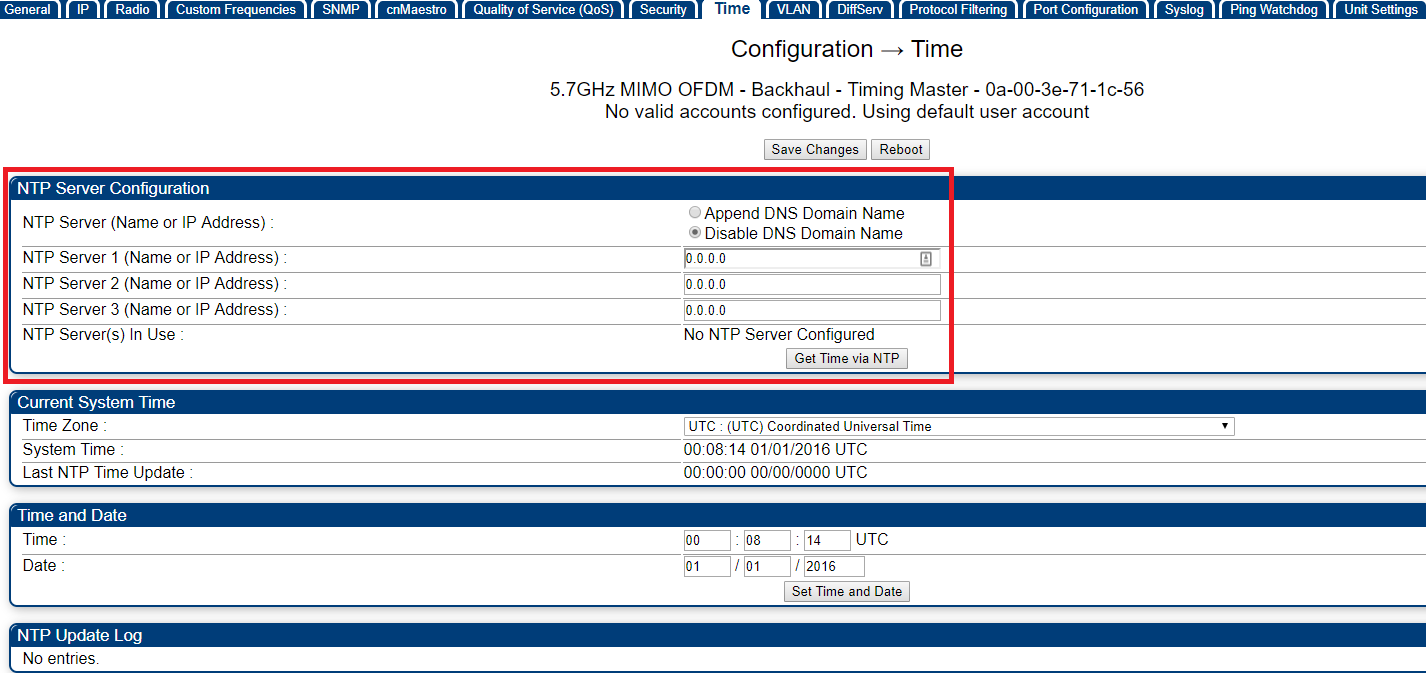
Under Configuration > Time configure up to three NTP servers for a network time source for the radio, or alternatively set the time and date manually:
Step 6:
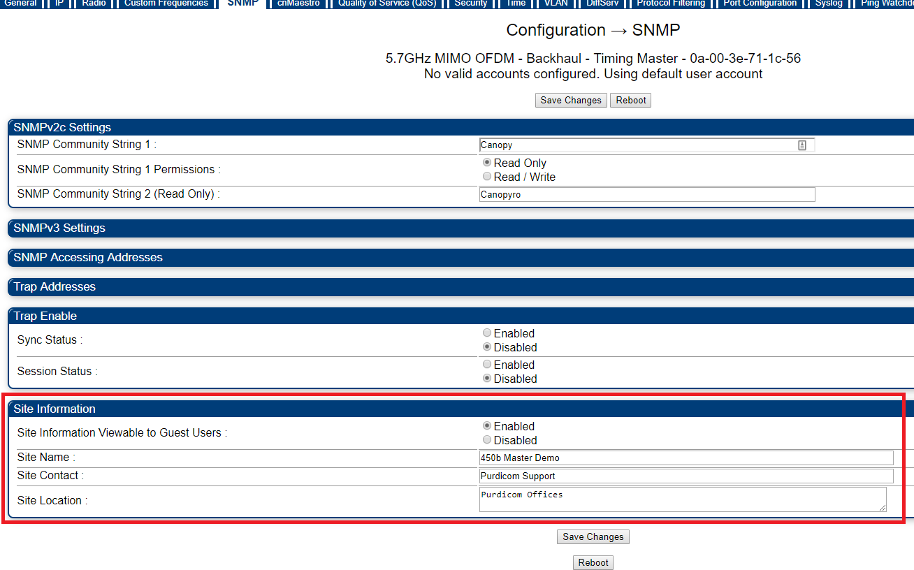
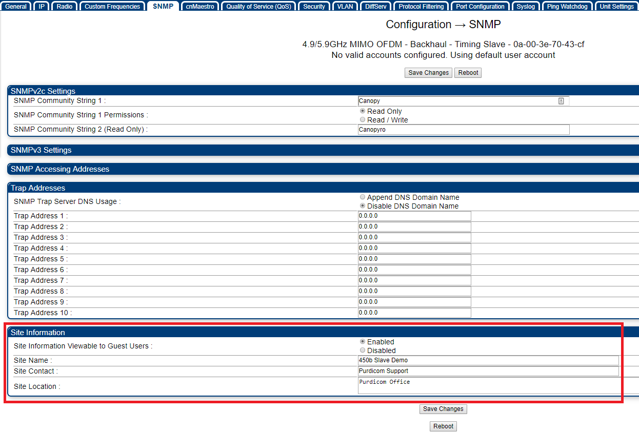
Under Configuration > SNMP > Site Information configure the device name, location and site contact:
Slave Configuration
Step 1:
Under Configuration > General > Region Settings configure the region and country code (this should be the same on both master and slave radios):
Step 2:
Under Configuration > Radio > Device Type configure the radio for Backhaul Mode. After saving the changes, configure the radio to be the Timing Slave:
Step 3:
Under Configuration > Radio > Radio Configuration select the frequencies and channel width used for operation – these settings must match the frequencies and channel width configured on the master radio:
Configure the desire transmit power under Configuration > Radio > Power Control:
NOTE: The transmit power and frequencies may require adjusting when deploying the link in the field as the RF environment will be different to that of the configuration bench.
Step 4:
Under Configuration > IP > LAN1 Network Interface Configuration configure the desired IP address, subnet mask, and default gateway for the radio. DNS server IP addresses can also be set here:
Step 5:
Under Configuration > Time configure up to three NTP servers for a network time source for the radio, or alternatively set the time and date manually:
Step 6:
Under Configuration > SNMP > Site Information configure the device name, location and site contact:
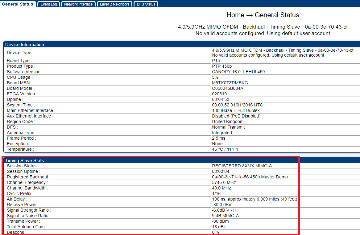
The link should now come up between both Master and Slave radio. This can be verfied under Home > General Status > Timing Slave Stats:

