Cambium 820S PTP 1+0 Configuration Wizard
Description:
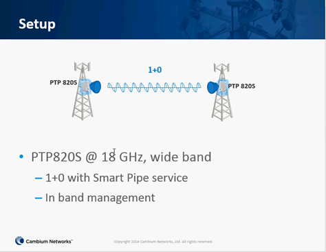
Guide to creating a basic Pipe 1+0 link using two PTP 820 S radios.
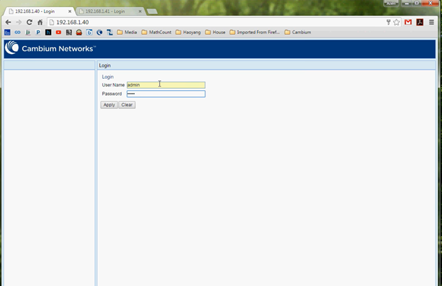
Step 1: Login
Navigate to the Web GUI page Default IP 192.168.1.1
However for this guide we have preconfigured with the following addresses,
Master End 192.168.1.40 – Slave End 192.168.1.41.
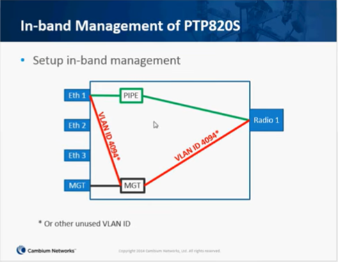
VLAN Management using VLAN 4094
Default Login Username: admin Password: admin
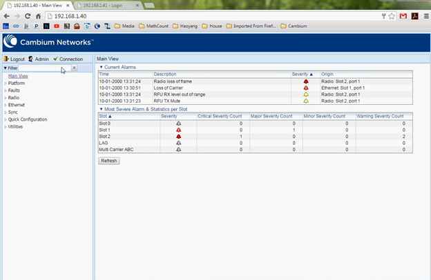
Main Dashboard
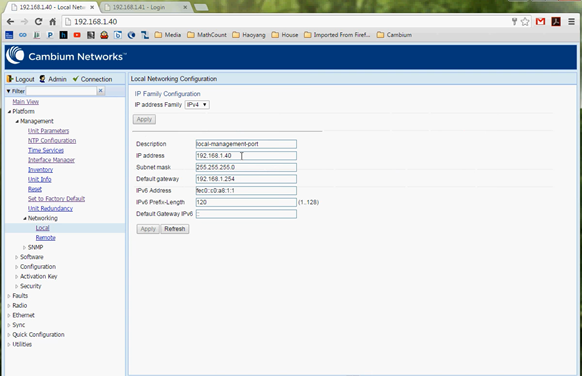
Step 2: Management IP Address
Navigate to Platform>Management>Networking>Local
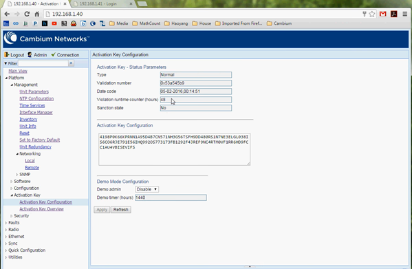
Step 3: Load the License Key
Platform>Management>Activation Key Configuration
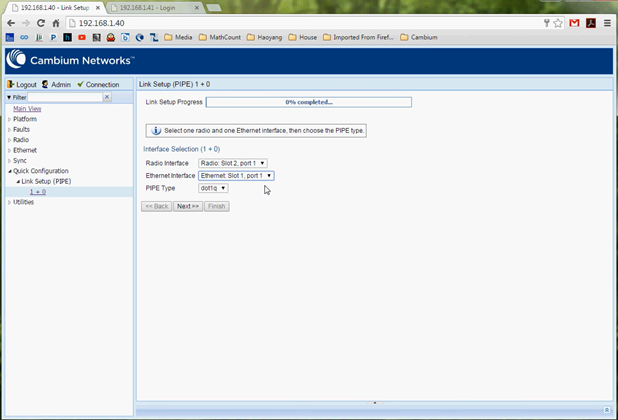
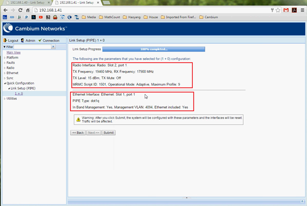
Step 4: Quick Configuration> Link Setup (PIPE)> 1 + 0
Radio Interface> Radio: Slot2 Port 1
Ethernet Interface> Ethernet: Slot1, port 1 or Ethernet: Slot 1, port 2
PIPE Type> dot1q or s-tag
s-tag – All S-VLANs and untagged frames are classified into the service.
dot1q – All C-VLANs and untagged frames are classified into the service
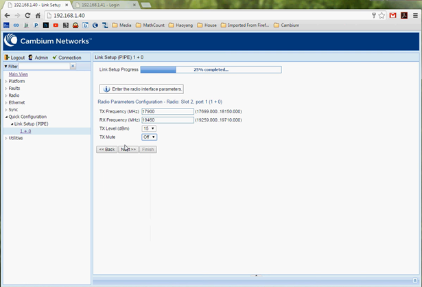
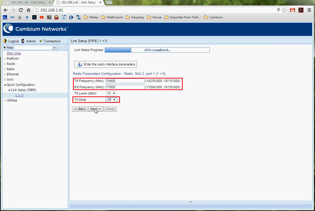
Step 5: Define the TX and RX frequencies as per your link requirement/license.
TX Mute: Off (In order to turn On transmit TX Mute needs to be set to off)
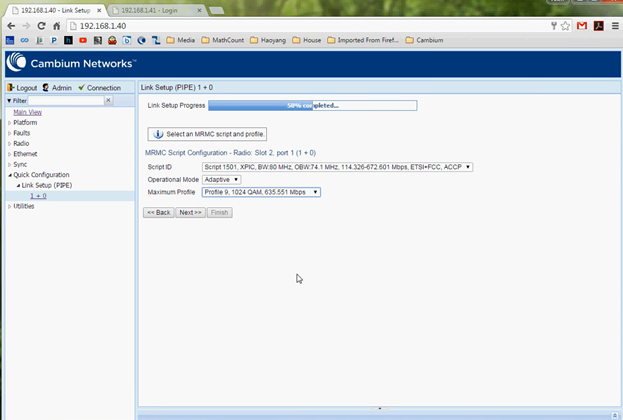
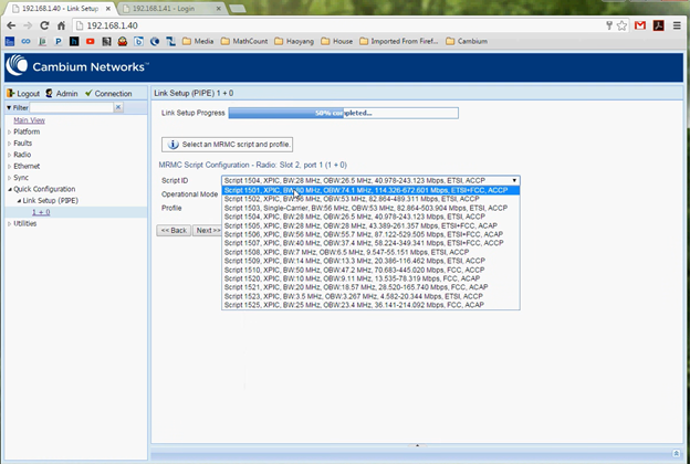
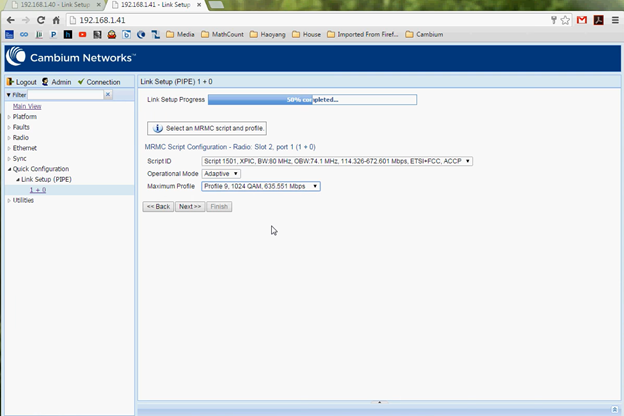
In the Script ID field, select the MRMC script you want to assign to the radio
Multi-Rate Multi-Constellation (MRMC) radio scripts define how the radio utilizes its available capacity. Each script is a pre-defined collection of configuration settings that specify the radio’s transmit and receive levels, link modulation, channel spacing, and bit rate. Scripts apply uniform transmit and receive rates that remain constant regardless of environmental impact on radio operation.
Select Operational Mode: Fixed or Adaptive (Modulation)
Fixed ACM mode applies constant TX and RX rates.
In Adaptive ACM mode, TX and RX rates are dynamic. An ACM-enabled radio system automatically chooses which profile to use according to channel fading conditions.
Select Maximum Profile: Dependent on Channel Size (License)
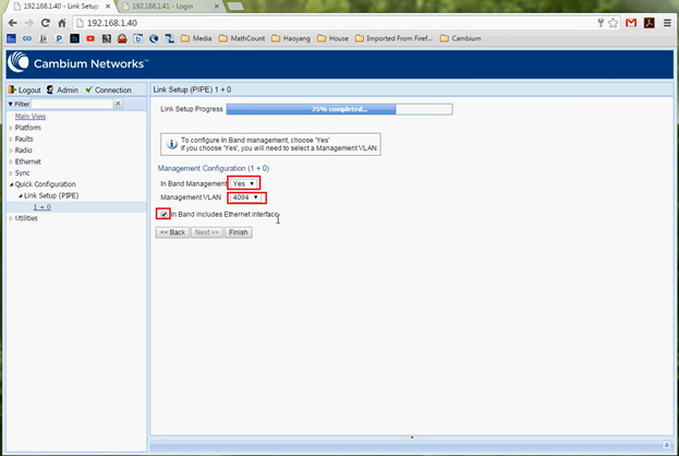
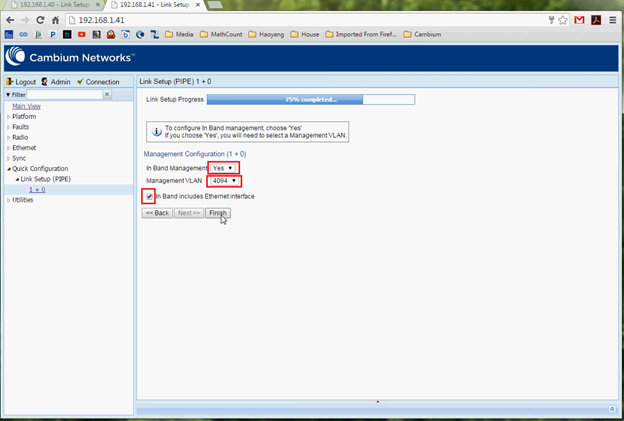
Step 6: Inband Management
Select In-Band Management > Yes
Select Management VLAN ID> (4094) (Replace VLAN ID with your desired VLAN ID)
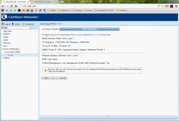
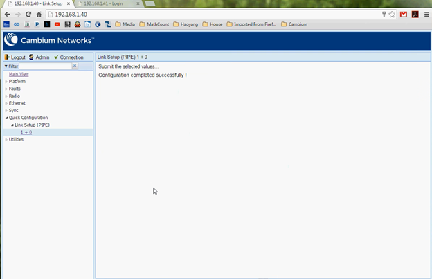
Review your summary page then click submit, the unit will reset.
Step 7: Slave Configuration:
Ensure the TX & RX frequencies are in the reverse order of the Master TX & RX frequencies.
TX Mute Set to Off to enable Transmit Power.
Step 8: Inband Management
Select In-Band Management > Yes
Select Management VLAN ID> (4094) (Replace VLAN ID with your desired VLAN ID)
Review the summary page and click submit, the unit will then reset.
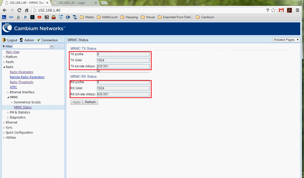
After both units have reset, log in and navigate to the MRMC Status (Radio>MRMC>MRMC Status)
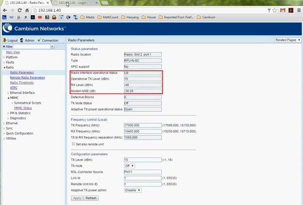
Then confirm the Radio Parameters – (Radio>Radio Parameters) Checking the Operational Status, RX Level & MSE
MSE: Mean Square Error, is a measure of interference, -40dB is typical where -99dB indicates no link. MSE values > -40dB indicates interference

